I. Introduction to Operation Panel Functions and Initialization Settings
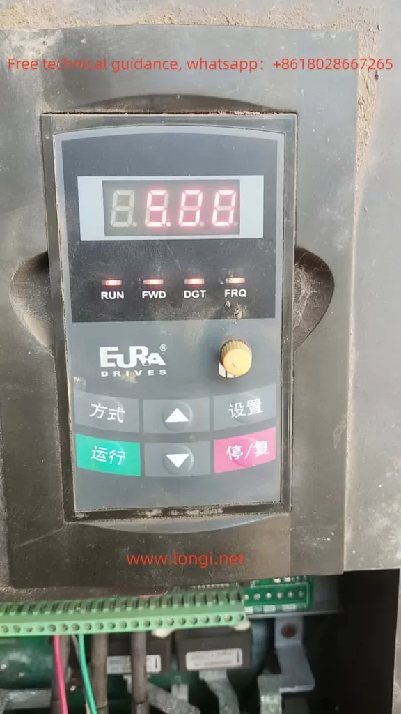
The EURA Inverter E2000 series comes equipped with an intuitive and user-friendly operation panel, enabling users to easily set parameters and monitor the inverter’s status. The operation panel typically includes a display screen, direction keys, function keys, and operation control keys.

Restoring Parameter Initialization Settings:
To restore the inverter’s parameters to their factory settings, users need to enter the programming menu and locate function code F160. The specific steps are as follows:
- Press the “Mode” key to display the function codes.
- Use the “Up” or “Down” key to select function code F160.
- Press the “Set” key to enter the setting value interface for F160.
- Change the setting value of F160 to 1 and press the “Set” key again to confirm.
At this point, the inverter will begin the initialization process, restoring all parameters to their factory default values.

Setting Passwords and Parameter Locking:
To ensure the security of parameter settings, the E2000 series inverter supports password protection and parameter locking functions. Users can enable or disable password protection by setting function code F107 and set the user password through F100. Once password protection is enabled, users must enter the correct password before modifying parameters.
Setting Reserved Parameter Areas:
The reserved parameter area allows users to save a set of parameters as a macro for quick recall. Users can select the saved macro by setting function code F135 and restore the user macro through F160.

II. Terminal Control and External Input
Terminal Forward/Reverse Control and External Potentiometer Given:
The E2000 series inverter supports forward/reverse control via terminals and frequency given by an external potentiometer. The specific settings are as follows:
- Forward/Reverse Control: It is necessary to set function codes F200 and F201 to select terminals as the source of start and stop commands. Simultaneously, set F202 to determine the direction of operation.
- External Potentiometer Given: It is necessary to set function code F203 to select the main frequency source X and choose analog input AI3 (i.e., external potentiometer) as the given source. Additionally, set F422 to select between panel potentiometer and remote panel potentiometer.
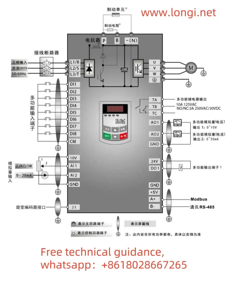
For wiring, users need to connect the output terminal of the external potentiometer to the AI3 terminal of the inverter and ensure proper grounding.
Pulse Input/Output Control:
The E2000 series inverter also supports pulse input/output control, suitable for applications requiring high-precision speed control. Users need to set function codes F440 to F449 to configure pulse input parameters such as minimum frequency, maximum frequency, filter constant, etc. Simultaneously, set F450 to F453 to configure pulse output parameters.
For wiring, users need to connect the output terminal of the pulse generator to the FI terminal of the inverter and connect the FO terminal of the inverter to the device receiving the pulse.
III. Fault Code Analysis and Solutions
The EURA Inverter E2000 series is equipped with a comprehensive fault protection mechanism, capable of real-time monitoring and reporting of various faults. Common fault codes include:
- OC: Overcurrent protection. Possible causes include motor jam, excessive load, etc. Solutions include checking the motor and load, extending acceleration time, etc.
- OE: DC overvoltage protection. Possible causes include excessive power supply voltage, brake unit failure, etc. Solutions include checking the power supply voltage, inspecting the brake unit, etc.
- OL1: Inverter overload protection. Possible causes include excessive load, poor heat dissipation, etc. Solutions include reducing the load, improving heat dissipation conditions, etc.
- OH: Inverter overheat protection. Possible causes include high ambient temperature, fan failure, etc. Solutions include improving ventilation conditions, replacing the fan, etc.
Users can view fault codes through the operation panel and follow the guidance in the manual for troubleshooting and resolution.
IV. Conclusion
The EURA Inverter E2000 series user manual provides a detailed operation guide covering operation panel function introduction, parameter setting, terminal control, fault troubleshooting, and other aspects. By carefully reading the manual and following the guidance, users can easily achieve the installation, commissioning, and maintenance of the inverter. At the same time, the fault code analysis and solutions in the manual also provide strong support for users, helping them quickly resolve issues that may arise during the operation of the inverter.
