
I. Introduction to VFD Operation Panel Functions
The operation panel of the Mitsubishi VFD FR-D700 series(D740,D720) is straightforward, facilitating various settings and operations for users. The panel primarily includes the following buttons and a rotary potentiometer:
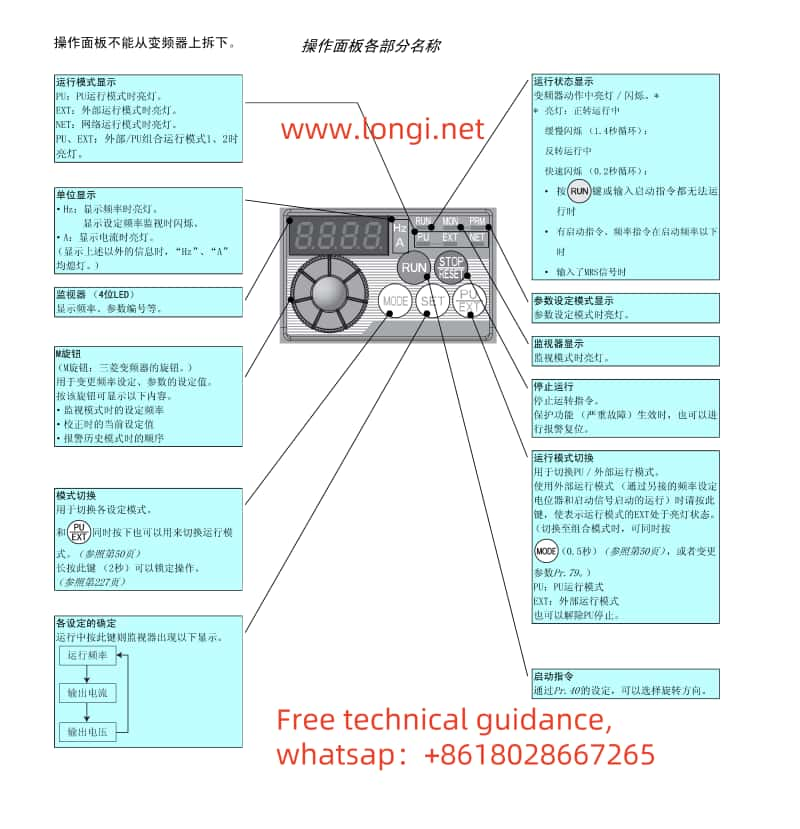
RUN: Press this button to start the VFD.
STOP/RESET: Press this button to stop the VFD or reset alarms.
MODE: Mode switching button used to toggle between different setting and display modes.
SET: Confirmation button used to confirm current settings or enter the next menu level.
PU/EXT: Operation mode switching button used to switch between PU (operation panel) mode and EXT (external terminal) mode.
Rotary Potentiometer: Used to manually adjust the output frequency of the VFD.
Setting Operation Modes
The VFD offers multiple operation modes, which can be set via parameter P79:
P79=0: PU operation mode, controlled via buttons and the rotary potentiometer on the operation panel.
P79=2: External operation mode, receiving start, stop, and speed commands via external terminals.
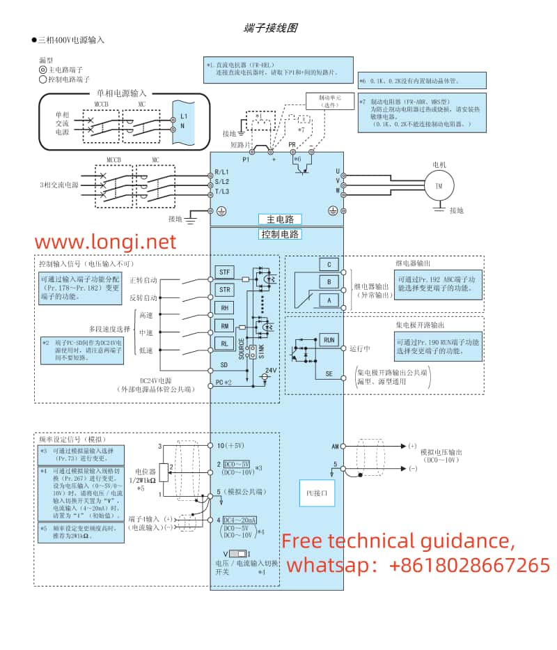
II. Terminal Start/Stop and External Potentiometer Speed Adjustment
Wiring Instructions
To achieve terminal start/stop and external potentiometer speed adjustment, proper wiring to the corresponding terminals of the VFD is required. Typically, the wiring is as follows:
STF (Forward Start): Connect to the normally open contact of an external start button or relay.
STR (Reverse Start): If reverse function is needed, connect to the normally open contact of an external reverse start button or relay.
SD (Stop): Connect to the normally closed contact of an external stop button or relay.
RH, RM, RL (Speed Setting): These terminals are typically used to connect an external potentiometer for speed adjustment. Among them, RH and RL are connected to the two ends of the potentiometer, and RM is connected to the sliding contact of the potentiometer.
Parameter Settings
Apart from proper wiring, relevant parameters need to be set to ensure the VFD operates as expected:
P79: Set to 2 to select external operation mode.
Pr7, Pr8: Set acceleration and deceleration times respectively to suit different application needs.
Pr9: Set the electronic overcurrent protection parameter to protect the VFD and motor from overcurrent damage.
III. VFD Fault Code Analysis and Solutions
When faults occur in the Mitsubishi VFD FR-D700 series, corresponding error codes are displayed, allowing users to analyze and resolve the faults. Below are some common fault codes and their solutions:
ER1: Overcurrent during acceleration. Check if the motor is overloaded, if there is a short circuit in the output, and if the acceleration time is set too short.
ER2: Overcurrent during constant speed. Check for sudden changes in load, and if there is a short circuit in the output.
ER3: Overcurrent during deceleration. Check for rapid deceleration, if there is a short circuit in the output, and if the motor’s mechanical brake is applied too early.
OL: Overspeed prevention (overcurrent). Check if the motor is overloaded.
TH: Motor overheat. Check if the motor is operating overloaded for a long time, if the ambient temperature is too high, and if the cooling system is functioning properly.
PS: PU stop. Check if the STOP button on the operation panel is pressed.
MT: Main circuit terminal abnormality. Check if the connections of the main circuit terminals are loose or damaged.
uV: Undervoltage protection. Check if the power supply voltage is too low, and if there is a large-capacity motor starting up causing instantaneous voltage drop.
Solutions
For overcurrent faults (ER1, ER2, ER3, OL): First, check if the motor and load are normal, then adjust acceleration time, deceleration time, and electronic overcurrent protection parameters.
For overheating faults (TH): Improve the motor’s cooling conditions, such as adding fans or lowering the ambient temperature.
For PU stop (PS): Confirm if the STOP button was pressed by mistake; if not, check the related control circuits.
For main circuit terminal abnormality (MT): Check and tighten the connections of the main circuit terminals, and replace if damaged.
For undervoltage protection (uV): Check if the power supply voltage is stable, and consider adding a power supply voltage stabilizing device.
The above is the operation guide for the Mitsubishi VFD FR-D700 series user manual, hoping to assist users in practical operations. If encountering other issues during use, it is recommended to refer to the detailed user manual of the VFD or contact professional technicians of longi for consultation.