I. Introduction to Operation Panel Functions and Parameter Initialization
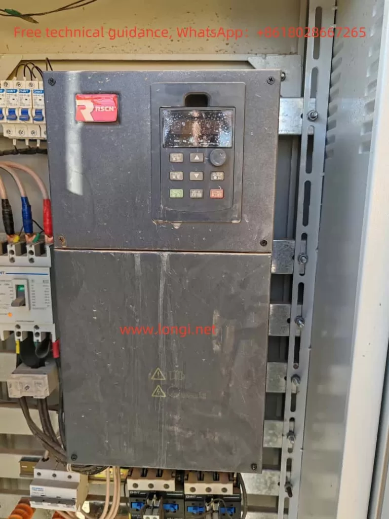
The Ruishen Inverter RCP900 series is equipped with an intuitive and user-friendly operation panel, which integrates a data display area, command source indicators, forward/reverse indicators, and various other functions. Through this panel, users can easily perform parameter settings, working status monitoring, operation control, and other operations of the inverter.

Parameter Initialization:
Before using the RCP900 series inverter, it is sometimes necessary to initialize the parameters to restore the factory settings. This can be achieved by setting the function code PP-01. Setting PP-01 to 1 will restore the inverter’s factory parameters (excluding motor parameters). This step is particularly important for resolving inverter faults caused by incorrect parameter settings.
Password Setting and Removal:
To protect the inverter settings from unauthorized changes, the RCP900 series inverter supports password protection. Users can set a password by configuring the function code PP-00. To remove the password, simply set PP-00 to 0. The password protection feature effectively prevents unauthorized operations and ensures the safety and stability of the inverter’s operation.
Parameter Access Restriction:
In addition to password protection, the RCP900 series inverter also supports parameter access restriction functionality. Users can select which parameter groups or specific parameters can be accessed and modified by configuring the function codes PP-03 and PP-04. This feature allows users to flexibly control access permissions to the inverter parameters based on actual needs, enhancing the security of device management.

II. Terminal Forward/Reverse Control and External Potentiometer Speed Regulation
Terminal Forward/Reverse Control:
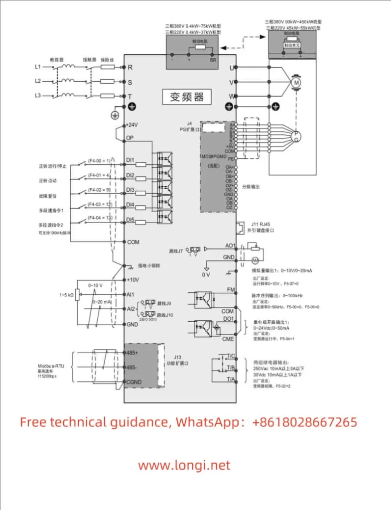
The RCP900 series inverter supports forward/reverse control of the motor through terminals. The specific wiring method is as follows: Connect the forward control signal to the DI1 terminal, the reverse control signal to the DI2 terminal, and the common terminal to the COM terminal. In terms of parameter settings, it is necessary to set P0-02 (Run Command Selection) to 1 (Terminal Command), P4-00 (DI1 Terminal Function Selection) to 1 (Forward Run), and P4-01 (DI2 Terminal Function Selection) to 2 (Reverse Run). After completing these settings, the motor’s forward/reverse control can be achieved by controlling the electrical level status of the DI1 and DI2 terminals.
External Potentiometer Speed Regulation:
The RCP900 series inverter also supports speed regulation through an external potentiometer. The specific wiring method is as follows: Connect the output end of the external potentiometer to the AI1 terminal and the GND terminal to the inverter’s GND terminal. In terms of parameter settings, it is necessary to set P0-03 (Main Frequency Command Input Selection) to 4 (AI3 Panel Potentiometer). After completing these settings, the motor speed can be adjusted by adjusting the resistance value of the external potentiometer.

III. Fault Code Meaning Analysis and Troubleshooting
During operation, the RCP900 series inverter may encounter various faults. When a fault occurs, the inverter will display the corresponding fault code. Below are some common fault codes, their meanings, and troubleshooting methods:
- Err02: Acceleration Overcurrent. Possible causes include grounding or short circuit in the output circuit, incorrect motor parameter settings, etc. Solutions include troubleshooting peripheral issues, performing motor parameter identification, etc.
- Err03: Deceleration Overcurrent. Possible causes are similar to those of acceleration overcurrent. Solutions also include troubleshooting peripheral issues, increasing deceleration time, etc.
- Err05: Acceleration Overvoltage. Possible causes include high input voltage, short acceleration time, etc. Solutions include adjusting the input voltage, increasing the acceleration time, etc.
- Err14: IGBT Overheat. Possible causes include high ambient temperature, fan failure, etc. Solutions include lowering the ambient temperature, replacing the fan, etc.
For the above fault codes, users can adopt corresponding solutions based on the inverter’s display information, combined with fault phenomena and possible causes. If the issue cannot be resolved, it is recommended to contact Ruishen Inverter’s technical support personnel or professional maintenance personnel for assistance.
IV. Conclusion
The Ruishen Inverter RCP900 series user manual provides a detailed operation guide, including operation panel function introduction, parameter initialization, password setting and removal, parameter access restriction, terminal forward/reverse control, external potentiometer speed regulation, fault code meaning analysis, troubleshooting methods, and other content. By carefully reading and understanding the user manual, users can better master the inverter’s usage methods and maintenance skills, ensuring the normal operation of the equipment and extending its service life. At the same time, users should flexibly utilize the inverter’s various functions based on actual needs to achieve more efficient and stable motor control.
