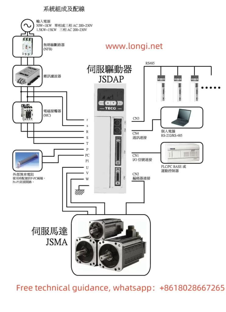
The TECO JSDAP series servo drive is a high-performance servo system widely applied in various industrial automation scenarios. To facilitate better operation and maintenance of the JSDAP series servo drive, this article will provide a detailed introduction to its status display and diagnostic functions, trial operation of the servo motor without load in conjunction with an upper-level controller, parameter reset, fan operation settings, position mode control, electronic gear ratio settings, and fault code analysis.

I. Status Display and Diagnostic Functions
Status Display Function
The status display function of the JSDAP servo drive is realized through the LED seven-segment display and LED lights on the panel. When the drive is powered on, the POWER indicator light on the panel illuminates, indicating that the drive is properly powered. The CHARGE indicator light remains lit until the main circuit is completely discharged after the power is turned off, reminding users not to touch the circuit or replace components at this time. Users can cycle through various parameters, including status display parameters, diagnostic parameters, abnormal alarm records, system parameters, torque control parameters, speed control parameters, and position control parameters, by pressing the MODE key.
Diagnostic Function
The diagnostic function allows users to view various information about the current system, such as the current control mode (dn-01), output contact signal status (dn-02), input contact signal status (dn-03), CPU software version (dn-04), etc. This diagnostic information is extremely helpful for troubleshooting and system debugging.
II. Trial Operation of Servo Motor Without Load in Conjunction with an Upper-Level Controller
Trial operation of the servo motor without load is an important step to verify the correctness of the drive configuration and wiring. Before trial operation, it is necessary to ensure that the drive power supply, motor wiring, and encoder wiring are all correct. During trial operation, the JOG function on the drive panel can be utilized to check the motor’s operating speed and direction.
Specific steps are as follows:
- Fix the servo motor onto the machine platform to prevent it from jumping or moving during trial operation.
- Check whether the drive power supply, motor wiring, and encoder wiring are correct. Remove the control signal wires (CN1).
- Turn on the drive power. If an abnormality is displayed on the panel, troubleshoot according to the abnormality code.
- Release the mechanical brake (if the motor is equipped with one).
- Use the panel to operate the JOG function and check whether the motor’s operating speed and direction are correct. If abnormalities are found, adjust the speed control parameters (such as Sn201) and system parameters (such as Cn004).
III. Parameter Reset and Fan Operation Settings

Parameter Reset
If a parameter reset is required for the drive, it can be achieved by simultaneously pressing the UP and DOWN keys on the panel. After resolving the abnormal alarm, first deactivate the input contact SON (i.e., deactivate the motor excitation state), then simultaneously press the UP and DOWN keys. The panel will display “RESET” and immediately return to the parameter selection screen, indicating that the abnormal alarm has been correctly cleared.
Fan Operation Settings
Fan operation settings are adjusted through relevant parameters. Specific setting methods are detailed in the relevant sections of the user manual. Generally, control parameters can be adjusted to set the fan’s start-up temperature and operation mode to ensure the drive operates at an appropriate temperature.
IV. Position Mode Control and Electronic Gear Ratio Settings
Position Mode Control
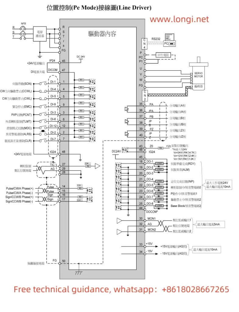
Position mode control is suitable for applications requiring precise control of the motor’s position. In position mode, the motor’s position is controlled by external pulse command signals. To achieve position mode control, correct wiring and parameter settings are required.
In terms of wiring, the pulse command signals (Pulse and /Pulse) and signal signs (Sign and /Sign) need to be connected to the corresponding contacts of the CN1 control signal terminal. Simultaneously, ensure that the drive power supply, motor wiring, and encoder wiring are all correct.
For parameter settings, the control mode selection parameter (Cn001) needs to be set to position control mode (usually 2 or 3), and the electronic gear ratio parameters (Pn302~Pn306) need to be set to adapt to different application requirements. The electronic gear ratio is used to convert pulse command signals into the motor’s actual movement distance.
Electronic Gear Ratio Settings
The setting of the electronic gear ratio is crucial for the accuracy of position control. By adjusting the electronic gear ratio parameters (Pn302~Pn306), the proportional relationship between the pulse command signal and the motor’s actual movement distance can be changed. Specific setting methods are detailed in the relevant sections of the user manual. Generally, the appropriate electronic gear ratio needs to be calculated and set based on the motor encoder’s specifications and the machine platform’s application specifications.
V. Fault Code Meaning Analysis and Troubleshooting
During operation, the JSDAP servo drive may display various fault codes. These codes typically indicate specific abnormal types, such as overvoltage, overcurrent, encoder abnormalities, etc. When a fault code appears, users should first consult the fault code table in the user manual to understand the abnormal type and its possible causes.
Troubleshooting methods usually include checking whether the wiring is correct, whether the parameter settings are reasonable, whether the external load is too heavy, etc. After resolving the fault, utilize the abnormal reset function on the drive panel to clear the abnormal alarm and restore the drive’s normal operation.
VI. Conclusion
This article provides a detailed introduction to the operation guide for the TECO JSDAP series servo drive user manual, covering status display and diagnostic functions, trial operation of the servo motor without load in conjunction with an upper-level controller, parameter reset, fan operation settings, position mode control, electronic gear ratio settings, and fault code analysis. By following the guidance in this article, users can better operate and maintain the JSDAP series servo drive, ensuring its stable and reliable operation in various industrial automation scenarios.
