The Yaskawa V1000 series inverter, as a high-performance vector control inverter, is widely used in various industrial drive systems. This article will provide a detailed introduction to the operation panel functions, basic setting methods, common function applications, and fault code analysis of this inverter, helping users better understand and utilize this equipment.

I. Introduction to Operation Panel Functions and Basic Settings
1. Introduction to Operation Panel Functions
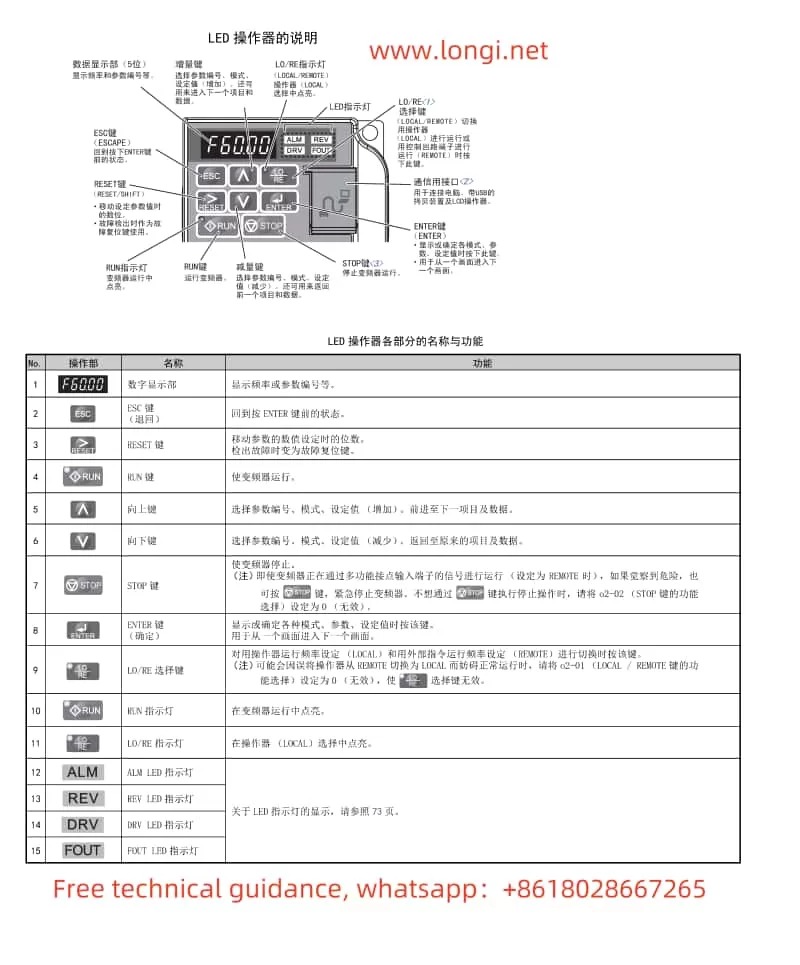
The operation panel of the Yaskawa V1000 series inverter integrates rich display and control functions, mainly including the LED operator, LO/RE indicator light, RUN indicator light, etc. Users can perform parameter settings, mode switching, operation monitoring, and other operations through the operation panel.
2. How to Set and Clear Passwords
To protect the inverter parameters from being modified arbitrarily, users can set a password. The specific steps are as follows:
- Setting a Password: In the parameter setting mode, find A1-04 (password setting), enter the desired password value, and then press the ENTER button to confirm. Next, enter the same password value in A1-05 (password) for confirmation.
- Clearing a Password: To clear the set password, simply set the password values in both A1-04 and A1-05 to 0.
3. Parameter Initialization
When it is necessary to restore the inverter to its factory default settings, parameter initialization can be performed. The specific steps are as follows:
- In the parameter setting mode, set A1-03 to 2220 (2-wire sequence control initialization) or 3330 (3-wire sequence control initialization), and then press the ENTER button to confirm. At this point, the inverter will be restored to its factory default settings.
4. Using the DWELL Function
The DWELL function can temporarily maintain the output frequency during motor startup or stoppage to prevent motor stall. The specific setting steps are as follows:
- In the parameter setting mode, find b6-01 and b6-02, and set the DWELL frequency and time during startup respectively. For example, set b6-01 to 5Hz and b6-02 to 2s, so that the motor will maintain a 5Hz output for 2 seconds during startup.
5. Using the Speed Search Function
The speed search function can automatically search and set the appropriate output frequency when the motor stalls or restarts. The specific usage method is as follows:
- In the parameter setting mode, set b3-05 to the speed search wait time (e.g., 1s). Then, trigger the speed search function through an external signal when needed, and the inverter will automatically search and set the appropriate output frequency.

II. Terminal Functions and Wiring Settings
1. Realizing Forward and Reverse Start/Stop Functions
To realize the forward and reverse start/stop functions of the motor, it is necessary to correctly wire and set relevant parameters. The specific steps are as follows:
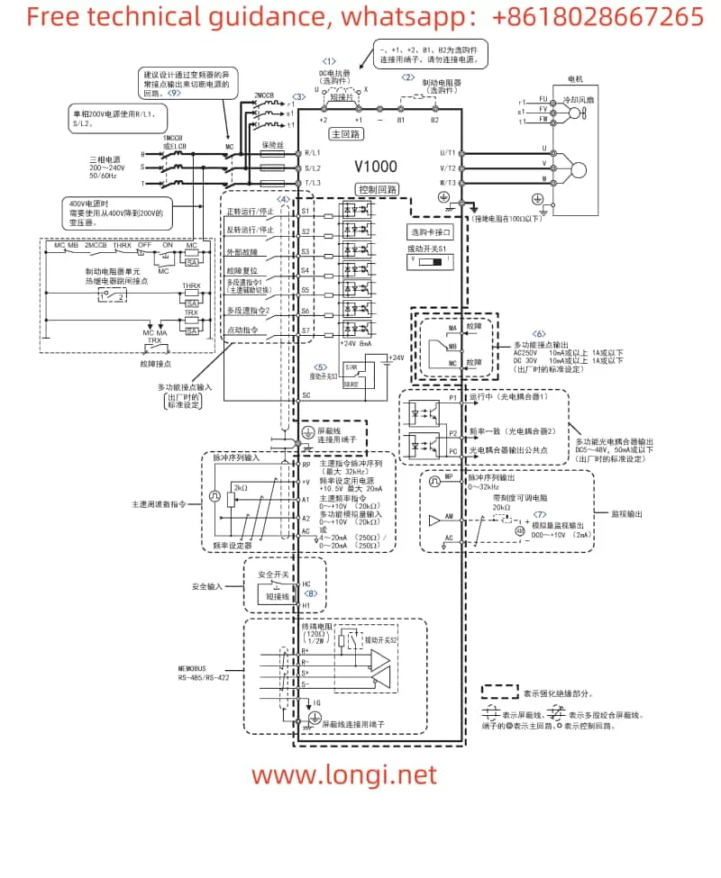
- Wiring: Connect the forward start signal to terminal S1, the reverse start signal to terminal S2, and the stop signal to terminal S3.
- Parameter Settings: In the parameter setting mode, set b1-02 to 1 (LOCAL/REMOTE selection), and set H1-01 and H1-02 to the input terminals for forward and reverse commands (e.g., S1 and S2) respectively. At the same time, set H1-03 to the input terminal for the stop command (e.g., S3).
2. Realizing External Potentiometer Speed Regulation
The external potentiometer speed regulation function allows users to change the output frequency of the inverter by adjusting the resistance value of an external potentiometer. The specific implementation method is as follows:
- Wiring: Connect the output signal of the external potentiometer to terminal A1 of the inverter (multi-function analog input terminal).
- Parameter Settings: In the parameter setting mode, set b1-01 to 1 (control circuit terminal frequency command), and set H3-01 to 0 (0~10V input). At the same time, adjust the values of H3-04 (input gain) and H3-05 (input offset) according to actual needs.
III. Fault Code Analysis
The Yaskawa V1000 series inverter has a comprehensive fault diagnosis function. When a fault occurs in the inverter, the corresponding fault code will be displayed on the operation panel. The following are some common fault codes, their meanings, and solutions:
- CPF02: A/D converter fault. Possible causes include control circuit damage, control circuit terminal short circuit, etc. Solutions include checking the control circuit connection and replacing the inverter.
- CPF06: EEPROM data anomaly. Possible causes include control circuit damage, power being cut off during the initialization process, etc. Solutions include re-executing the initialization operation and replacing the inverter.
- Uv1: Main circuit undervoltage. Possible causes include too low power supply voltage, power supply phase loss, etc. Solutions include checking the power supply voltage and power supply wiring.
- oH1: Heatsink overheat. Possible causes include too high ambient temperature, excessive load, etc. Solutions include improving heat dissipation conditions and reducing the load.
When a fault occurs in the inverter, users should refer to the fault code displayed on the operation panel, combine the above analysis methods and solutions for troubleshooting and handling. If the problem cannot be solved, users should promptly contact professional technicians for repair.
IV. Conclusion
The Yaskawa V1000 series inverter, as a high-performance vector control inverter, boasts rich functions and flexible setting options. Through the introduction in this article, users can better understand and utilize this equipment to achieve precise motor control and efficient operation. At the same time, users should also regularly check and maintain the inverter to ensure its long-term stable operation.
