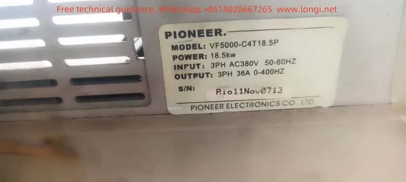
The PIONEER VF5000 series high-performance vector inverter is an advanced inverter featuring high torque, high precision, and a wide speed range. It is widely used in various mechanical equipment and speed control systems. This article will provide a detailed introduction to the inverter’s operation panel functions, parameter settings, external terminal wiring, and fault handling methods.

I. Operation Panel (Keyboard) Function Introduction and Parameter Settings
1.1 Operation Panel Functions
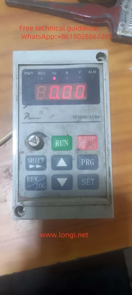
The PIONEER VF5000 series inverter is equipped with an intuitive and easy-to-use operation panel. The main button functions are as follows:
- RUN Key: Used to start or stop the inverter.
- STOP/RESET Key: Press this key to stop the inverter during normal operation, or to reset faults in the fault state.
- PRG Key: Enters or exits the programming state for modifying function parameters.
- JOG/REV Key (Not available on LC03): Used for jogging or reversing the motor.
- ▲ (Increase) Key and ▼ (Decrease) Key: Used to modify parameter values in the programming state.
- SET Key: Saves modified parameter values.
- ► (Shift) Key: Selects the parameter bit to be modified in the programming state.
- Analog Potentiometer: When F0.01 is set to 0, adjusting this potentiometer changes the output frequency.
1.2 Password Setting and Clearance
The PIONEER VF5000 series inverter provides a parameter write protection feature, which can be set via the F3.02 parameter to prevent unauthorized parameter modifications. Password setting and clearance must be performed in the programming state. Please refer to the parameter setting section in the user manual for specific methods.
1.3 Parameter Initialization
Parameter initialization restores the inverter to its factory settings. In the programming state, set the F3.01 parameter to 1 to restore factory defaults. Note that this operation will clear all user-defined parameters and should be used with caution.
1.4 Jogging Operation
Jogging operation allows the user to achieve short-term frequency conversion through the operation panel or external terminals. In the programming state, set the F0.04 parameter to operation panel control, set the F2.19 parameter for the jogging frequency, and then press the jogging key on the operation panel to enable jogging.

1.5 Closed-Loop PID Control Wiring and Settings
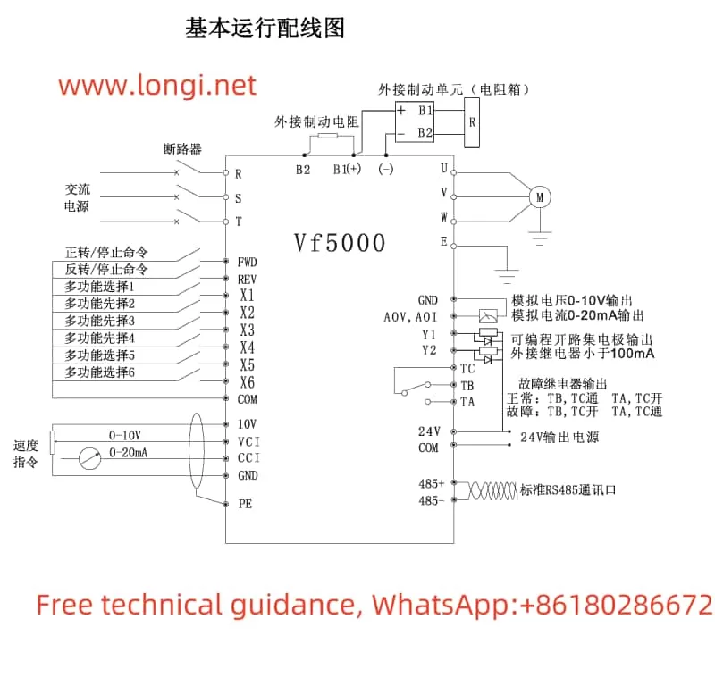
To achieve closed-loop PID control, the feedback signal from the pressure sensor should be connected to the CCI terminal of the inverter, and the setpoint signal to the VCI terminal. Please refer to the wiring diagram in the user manual for specific wiring methods. In the programming state, set the F6.00 parameter to enable PID function, F6.01 and F6.02 parameters to select the setpoint and feedback channels respectively, and F6.06, F6.07, and F6.08 parameters to set the PID control’s proportional, integral, and derivative times.
II. External Terminal Wiring and Parameter Settings
2.1 Forward and Reverse Start
To achieve forward and reverse start via external terminals, connect the control terminals FWD and REV to the forward and reverse start signal sources respectively. In the programming state, set the F0.04 parameter to terminal operation command channel, and the F4.06 parameter to select the two-wire or three-wire control mode. Please refer to the wiring diagram in the user manual for specific wiring methods.
2.2 External Potentiometer Speed Control
For external potentiometer speed control, connect the sliding end of the potentiometer to the VCI terminal of the inverter, and the other two fixed ends to the +10V and GND terminals respectively. In the programming state, set the F0.01 parameter to VCI analog setpoint to change the output frequency by adjusting the external potentiometer.

III. Fault Code Meaning Analysis and Solutions
The PIONEER VF5000 series inverter features comprehensive fault protection. When a fault is detected, the inverter will stop outputting and display the corresponding fault code. Common fault codes, their meanings, and solutions are as follows:
- E-01: Overcurrent during acceleration. Possible causes include too short an acceleration time, excessive load inertia, etc. Solutions include extending the acceleration time, reducing load inertia, etc.
- E-02: Overcurrent during deceleration. Possible causes include too short a deceleration time, large inertial loads, etc. Solutions include extending the deceleration time, reducing load inertia, etc.
- E-12: Inverter overload. Possible causes include excessive torque boost, excessive load, etc. Solutions include reducing the torque boost value, reducing the load, etc.
Please refer to the fault diagnosis and handling section in the user manual for detailed fault codes and countermeasures.
IV. Conclusion
The PIONEER VF5000 series high-performance vector inverter boasts powerful functions and easy operation. By reasonably setting the operation panel parameters and external terminal wiring, various complex control requirements can be achieved. Meanwhile, the comprehensive fault protection function also provides a strong guarantee for the stable operation of the equipment. It is hoped that this user guide can help users better understand and use the VF5000 series inverter.
