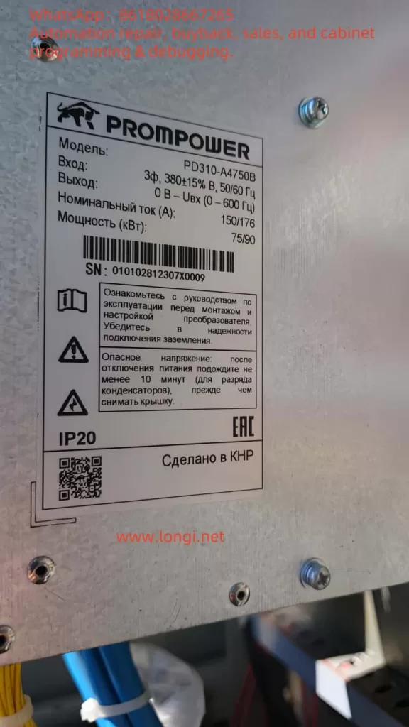
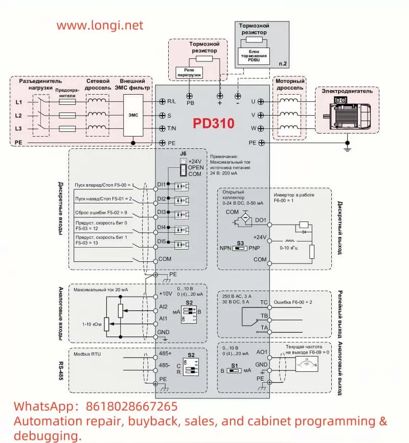
The PROMPOWER Inverter PD310 Series is a powerful and versatile low-voltage inverter suitable for industrial automation scenarios that require high dynamic performance and a wide range of speed regulation. To help users better master its usage, this document provides a detailed English user guide based on the Russian user manual. The content covers the functions of the operation panel and related settings, external control implementation methods, and diagnostic and handling procedures for fault codes.
I. Introduction to Operation Panel Functions and Related Settings
The operation panel is the core tool for user interaction with the PD310 Series inverter. Through its keys and display, users can perform operations such as parameter viewing, modification, and device control. This section will introduce the functions of the operation panel in detail and explain how to restore factory settings for parameters, set and eliminate passwords, and set parameter access restrictions.
1.1 Introduction to Operation Panel Functions

The operation panel of the PD310 Series inverter includes a display and multiple function keys for displaying the running status and executing operations. According to Chapter 5 “Приступаем к работе” (Getting Started) of the manual, the main functions are as follows:
- Display: Displays the current running status (such as frequency, voltage), parameter values, and fault codes.
- Key Functions:
- PRG (Programming Key): Enters or exits the programming mode to access the parameter setting menu.
- ENTER (Confirm Key): Confirms parameter modifications or enters the next level of the menu.
- UP (Up Key): Increases the parameter value or scrolls up the page.
- DOWN (Down Key): Decreases the parameter value or scrolls down the page.
- SHIFT (Shift Key): Switches between the parameter number and parameter value.
- RUN (Run Key): Starts the inverter.
- STOP/RESET (Stop/Reset Key): Stops the inverter operation or resets the fault status.
Operation Example: To modify a parameter, the user can press the PRG key to enter the programming mode, use the UP/DOWN keys to select the parameter number, press the ENTER key to enter the parameter value editing mode, use the UP/DOWN keys to adjust the value, and finally press the ENTER key to save.
1.2 Restoring Factory Settings for Parameters
To restore the inverter parameters to the factory default values, follow the steps in Section 5.3 “Сброс на заводские настройки” (Restoring Factory Settings) of the manual:
- Press the PRG key to enter the programming mode.
- Use the UP/DOWN keys to select the parameter group “F0”.
- Press the ENTER key to enter the “F0” group.
- Select the parameter “F0-00” (usually the factory reset parameter).
- Press the ENTER key to enter the editing mode and set the value to “1” (indicating factory reset).
- Press the ENTER key to confirm. The inverter will automatically restart, and the parameters will be restored to the factory values.
Note: This operation will clear all user settings. It is recommended to back up important parameters in advance.
1.3 Setting and Eliminating Passwords
The PD310 Series supports password protection to prevent unauthorized parameter modifications. The steps for setting and eliminating passwords are as follows:
- Setting a Password:
- Press the PRG key to enter the programming mode.
- Select the parameter group “F0”.
- Enter the parameter “F0-01” (password setting parameter).
- Input a 4-digit password (e.g., 1234) and adjust the value using the UP/DOWN keys.
- Press the ENTER key to confirm. The password setting takes effect.
- The password must be entered the next time parameter access is required.
- Eliminating a Password:
- Press the PRG key to enter the programming mode.
- Input the current password to unlock parameter access.
- Enter the parameter “F0-01”.
- Set the value to “0”.
- Press the ENTER key to confirm. The password is cleared.
1.4 Setting Parameter Access Restrictions
To prevent accidental operations, the PD310 allows restricting access permissions for certain parameters. The specific operations are as follows:
- Setting Access Restrictions:
- Press the PRG key to enter the programming mode.
- Select the parameter group “F0”.
- Enter the parameter “F0-02” (access restriction setting).
- Set the parameter value to the number of the parameter group to be restricted (e.g., set to “1” to restrict the F1 group).
- Press the ENTER key to confirm. The restricted parameter group cannot be accessed or modified.
- Lifting Access Restrictions:
- Press the PRG key to enter the programming mode.
- Input the password (if set) to unlock.
- Enter the parameter “F0-02”.
- Set the value to “0”.
- Press the ENTER key to confirm. All parameter groups resume accessible status.
Through the above settings, users can flexibly manage parameter permissions and ensure system security.

II. External Control Implementation
The PD310 Series inverter supports motor forward/reverse control and speed regulation through external terminals. This section will introduce how to achieve external terminal forward/reverse control and external potentiometer speed regulation through wiring and parameter settings.
2.1 External Terminal Forward/Reverse Control
External terminal forward/reverse control is achieved through digital input terminals (DI) and the common terminal (COM). According to Section 4.5 “Клеммы управления” (Control Terminals) of the manual:
- Wiring:
- Forward Switch: Connect DI1 and COM terminals.
- Reverse Switch: Connect DI2 and COM terminals.
- Parameter Settings:
- Press the PRG key to enter the programming mode.
- Select the parameter group “F1”.
- Set “F1-00” (control mode) to “1” (terminal control).
- Set “F1-01” (DI1 function) to “1” (forward command).
- Set “F1-02” (DI2 function) to “2” (reverse command).
- Press the PRG key to exit.
- Operation Mode: When DI1 is closed, the motor runs forward; when DI2 is closed, the motor runs reverse. If both DI1 and DI2 are closed simultaneously, the motor may stop (depending on the parameter configuration).
2.2 External Potentiometer Speed Regulation
External potentiometer speed regulation achieves speed adjustment through analog input terminals (AI). According to Section 4.5 of the manual:
- Wiring:
- Potentiometer Middle Tap: Connect to the AI1 terminal.
- Potentiometer One End: Connect to the +10V terminal.
- Potentiometer Other End: Connect to the GND terminal.
- Parameter Settings:
- Press the PRG key to enter the programming mode.
- Select the parameter group “F2”.
- Set “F2-00” (speed reference method) to “1” (AI1 analog input).
- Set “F2-01” (AI1 minimum input) to 0V (minimum potentiometer voltage).
- Set “F2-02” (AI1 maximum input) to 10V (maximum potentiometer voltage).
- Set “F2-03” (AI1 minimum frequency) to 0Hz.
- Set “F2-04” (AI1 maximum frequency) to 50Hz (or the maximum frequency required by the user).
- Press the PRG key to exit.
- Operation Mode: Rotating the potentiometer linearly adjusts the motor speed from 0Hz to 50Hz.
III. Fault Codes and Handling
The PD310 Series inverter may encounter faults during operation and prompt the user with fault codes. This section lists common fault codes and their meanings based on Section 6.1 “Коды ошибок” (Fault Codes) of the manual and provides handling methods.
3.1 Fault Code List
The following are common fault codes and their meanings (refer to page 201 of the manual):
- Err01: Short-circuit protection (inverter output short-circuit).
- Err08: Overvoltage during acceleration.
- Err09: Overvoltage during deceleration.
- Err10: Overvoltage at constant speed.
- Err11: Undervoltage.
- Err12: Input phase loss.
- Err13: Output phase loss.
- Err14: Inverter overload.
- Err15: Motor overload.
- Err17: Inverter overtemperature.
- Err21: External fault.
- Err23: Communication fault.
3.2 Fault Handling Methods
For the above faults, the following are the recommended handling methods:
- Err01 Short-circuit Protection:
- Check if the motor and output lines are short-circuited.
- Ensure correct wiring and eliminate grounding faults.
- Err08/Err09/Err10 Overvoltage Faults:
- Check if the input voltage is too high.
- Confirm if the braking resistor is correctly connected or damaged.
- Extend the acceleration/deceleration time parameters (F0 group).
- Err11 Undervoltage:
- Check if the power supply voltage is below the requirement.
- Check if the power supply line connections are good.
- Err12 Input Phase Loss:
- Check if the three phases of the input power are complete.
- Ensure secure wiring.
- Err13 Output Phase Loss:
- Check if the motor wiring is loose or disconnected.
- Verify if the motor is normal.
- Err14 Inverter Overload:
- Reduce the load or replace with a higher-power inverter.
- Check if the parameter settings are reasonable.
- Err15 Motor Overload:
- Check if the load exceeds the motor capacity.
- Adjust the motor protection parameters (F5 group).
- Err17 Inverter Overtemperature:
- Check if the cooling fan is operating normally.
- Clean the heat sink to ensure good ventilation.
- Err21 External Fault:
- Check if the external fault input terminal (DI) is triggered.
- Eliminate the external fault source.
- Err23 Communication Fault:
- Check if the communication line connections are correct.
- Verify if the communication parameters (F11 group) match.
Handling Process: When a fault occurs, record the code and press the STOP/RESET key to reset. If the issue cannot be resolved, troubleshoot according to the above methods and contact PROMPOWER technical support if necessary.
Conclusion
Through this document, users can fully understand the operation and application of the PROMPOWER Inverter PD310 Series. The functions of the operation panel provide convenience for parameter management, and restoring factory settings, password protection, and access restrictions enhance system security. External terminal forward/reverse control and potentiometer speed regulation provide users with flexible control methods. The identification and handling methods for fault codes help quickly resolve issues and ensure stable equipment operation. This document aims to provide users with practical guidance and improve equipment usage efficiency.
