
I. Introduction to Operation Panel Functions and Password & Parameter Settings
The operation panel of the Ribbo Inverter RB5000 series is designed to be intuitive and user-friendly, facilitating various operations and settings. The panel mainly includes keys such as PRG/DRIVE, ▲▼, SET, RUN, STOP, JOG, MENU, and multiple indicator display windows.
Password Setting and Cancellation: The RB5000 series inverter does not directly mention a password setting function, but certain parameters in the High-level Parameter Group (HP) may involve access restrictions. To set similar password-like access restrictions, the HP-03 parameter can be modified to set the parameter group modification permissions. For example, setting HP-03 to a non-zero value will restrict access and modification to the AP, LP, HP, and PP parameter groups.
Parameter Access Restriction: By setting the HP-03 parameter, users can restrict access and modification permissions to the inverter parameters. For instance, when HP-03=0, all parameter groups can be viewed and modified; when HP-03=1, only the AP parameter group can be viewed and modified, while the other parameter groups can only be viewed.
Restoring Factory Default Settings: To restore the inverter parameters to their factory settings, the HP-03 parameter can be set to 07 or 08, which will not only restore all parameters to their factory defaults but also set the inverter to two-wire or three-wire start/stop control mode.
II. Terminal Forward/Reverse Control and External Potentiometer Speed Regulation
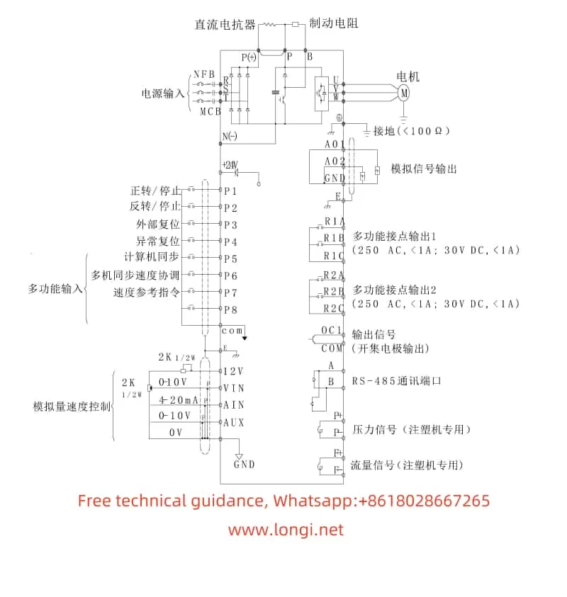
Terminal Forward/Reverse Control: The RB5000 series inverter supports motor forward/reverse control through external terminals. First, the control mode needs to be set to terminal control by setting the HP-04 parameter to 1. Then, depending on the requirements, the HP-03 parameter can be set to select two-wire or three-wire control mode. In two-wire control mode, terminal X1 is the forward start/stop command, and terminal X2 is the reverse start/stop command. In three-wire control mode, terminal X1 is the forward start command, terminal X2 is the reverse start command, and terminal X5 is the stop command.
External Potentiometer Speed Regulation: To regulate speed using an external potentiometer, the frequency command source needs to be set to external analog input by setting the HP-05 parameter to 1. Then, connect the external potentiometer to the VS terminal (voltage input, 0-10V) and GND terminal (common ground). Depending on the output characteristics of the potentiometer, the LP-05 (analog voltage frequency command gain) and LP-06 (analog voltage frequency command offset) parameters may also need to be adjusted to ensure that the speed regulation range matches the potentiometer output range.
III. Fault Codes and Troubleshooting
The RB5000 series inverter features comprehensive fault protection and alarm functions. When a fault occurs, the inverter will display a fault code through the LED to help users quickly locate the problem. Below are some common fault codes, their meanings, and troubleshooting methods:
- UE1 (UE): Under-voltage on the DC side of the main circuit. Possible causes include insufficient power supply capacity, excessive voltage drop in power supply lines, and power contactor failure. Solutions include checking the power supply voltage, power supply lines, and contactor.
- OE: Over-voltage on the DC side of the main circuit. Possible causes include too short a deceleration time, excessively high input voltage, or voltage spikes. Solutions include increasing the deceleration time, checking the input voltage, and ensuring power supply stability.
- OH: Internal overheating of the inverter. Possible causes include a malfunctioning cooling fan, poor ventilation, and blocked heat dissipation channels. Solutions include checking the cooling fan, improving ventilation, and clearing heat dissipation channels.
- OC: Output current of the inverter exceeds 200% of the rated value. Possible causes include too short an acceleration time, excessively large motor capacity, output short circuit or grounding. Solutions include increasing the acceleration time, checking the motor and output lines.
- OL1: Motor output overload. Possible causes include improper setting of the rated current and long-term motor overload. Solutions include adjusting the rated current setting and checking the motor load.
When a fault occurs, users should refer to the fault code and fault phenomenon, combined with the fault analysis and troubleshooting methods in the user manual, to troubleshoot and resolve the issue step-by-step. If the problem cannot be resolved independently, users can contact Ribbo Electric’s customer service center or distributor for assistance.
IV. Conclusion
The Ribbo Inverter RB5000 series user manual provides a detailed operation guide and troubleshooting methods, helping users better understand and use the inverter. Through this guide, users should be able to master the basic functions of the operation panel, parameter setting methods, terminal control and external speed regulation implementation, as well as fault code interpretation and troubleshooting. In practical applications, users should strictly follow the operating instructions and safety precautions in the user manual to ensure the normal operation and safe use of the inverter.