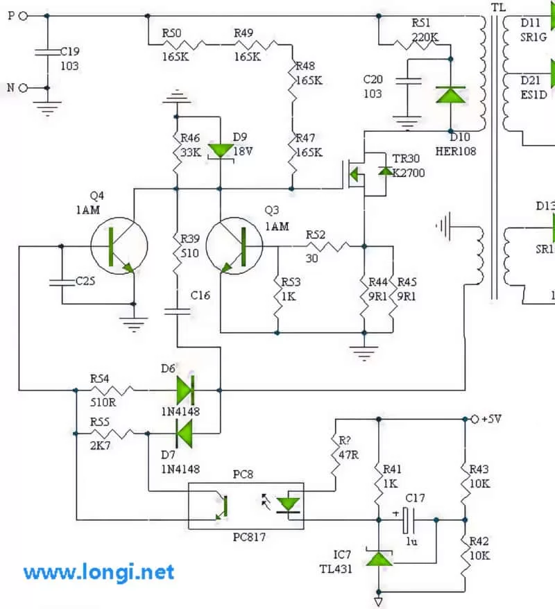
When dealing with the repair of a 22kW HC1 drive, it’s crucial to approach the process methodically, especially when encountering complex issues such as a blown fuse in the inverter module power supply series connection. This particular case study illustrates the step-by-step diagnosis and resolution of such a problem, highlighting the importance of thorough inspection and precise troubleshooting.

Initial Diagnosis and Fuse Replacement
The initial indication of trouble was the blown fuse in the inverter module’s power supply series connection. With no other abnormalities detected in the main circuit measurements, it was tempting to assume that simply replacing the fuse would resolve the issue. However, upon reinstalling the fuse and powering the inverter to 24V, the system immediately triggered an EOCn error code, indicating an overcurrent during acceleration or a short circuit on the motor side. This clear sign of ongoing malfunction signaled that the problem was more complex than just a blown fuse.
In-Depth Investigation of the Driver Circuit
With the fuse replacement failing to solve the issue, the next step was to dismantle and recheck the driver circuit board. A meticulous examination revealed that one of the driver circuits was not outputting a positive excitation pulse. Further investigation led to the discovery of a faulty power amplifier tube (lower tube) in the driver circuit. This component had broken down, causing the voltage terminal of the module trigger terminal to be continuously embedded in negative pressure.
The faulty amplifier tube was replaced, and the pulse circuit returned to normal operation. This repair seemed promising, so the machine was reassembled, connected to a 24V power supply, and powered on. However, the system immediately tripped with an EfbS error, indicating that the fuse had blown again.
Further Diagnostic Measures
To pinpoint the exact cause of the repeated fuse blowing, the 24V power supply was removed, and the original fuse terminals were replaced with light bulbs in series. This setup allowed for visual confirmation of power transmission, with the bulbs emitting strong light upon power-up. During a power outage, the trigger terminal was removed, and individual measurements of the module showed no abnormalities.
With the fuse replaced once more and the inverter circuit reconnected to the 24V power supply, the frequency converter was started. As the frequency rose to around 5Hz, the ECOn error would still trip, indicating persistent issues. At this point, it was unclear whether the problem lay in the module or the driver circuit.
Comprehensive Module and Driver Circuit Testing
To further narrow down the problem, the positive and negative voltage and current of the drive output were checked, and both were found to be normal. This finding suggested a possible module malfunction. To confirm this, all three modules were removed and placed on a workbench for power testing alongside the driver board.
Upon powering on the setup, it was observed that the negative pressure on one arm was unusually low, approximately 2V. Disconnecting the trigger terminal restored the negative pressure to its normal value. However, when the module trigger terminal was reinserted, the negative pressure decreased again. This confirmed that the module was indeed damaged.
Final Resolution
With the damaged module identified, it was replaced with a new one. After reinstalling the repaired components, the system was powered on and tested. This time, there were no error codes, and the drive operated smoothly without any issues. The fault had been successfully repaired, and the 22kW HC1 drive was restored to full functionality.
Conclusion
This case study underscores the importance of a systematic and thorough approach to troubleshooting and repairing complex electronic systems like the 22kW HC1 drive. By carefully examining each component and testing various scenarios, the root cause of the malfunction was identified and resolved. It also highlights the value of using diagnostic tools and techniques, such as replacing fuse terminals with light bulbs, to visually confirm power transmission and isolate faulty components. In the end, a combination of meticulous inspection, precise testing, and replacing damaged components led to a successful repair.
