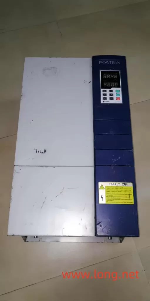
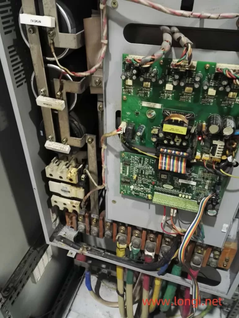
Repairing a PI-18 type 11kW POWTRAN VFD (Variable Frequency Drive) can be a challenging task, especially when dealing with OC (Overcurrent) alarms. This comprehensive guide aims to provide a structured and logical approach to diagnosing and fixing OC alarms in this specific VFD model, integrating both practical experiences and technical insights from various sources.

Understanding the OC Alarm
The OC alarm in a VFD typically indicates an overcurrent condition, which can be caused by various factors, including module damage, faulty driving circuits, or incorrect trigger pulses. In the PI-18 type 11kW POWTRAN VFD, the OC alarm often involves complex diagnostics due to the intricate interplay of its components.
Initial Diagnostics
1. Module Inspection:
The first step in troubleshooting an OC alarm is to inspect the inverter module. Damage to the module isn’t always apparent through simple visual inspection or basic electrical tests. It’s crucial to check for short circuits or open circuits not only in the main current terminals (R, S, T, U, V, W) but also between the triggering terminals and the main terminals, as well as within the triggering terminals themselves.
2. Measuring with a Multimeter:
While measuring the main terminals for short circuits is a good start, it doesn’t guarantee that the module is free from damage. Hidden issues such as leakage currents or degraded performance can still be present. Therefore, a more thorough approach is needed, including verifying the quality of the module under controlled conditions.
Detailed Diagnostics
1. Power-On Testing:
Before connecting the module to the full DC bus voltage, it’s advisable to perform a power-on test using a lower DC voltage. This can be achieved by using a 24V switching power supply. This step helps to identify any potential issues without risking further damage to the module or the drive.
2. Checking the Driving Circuit:
The driving circuit plays a critical role in the operation of the VFD. It’s essential to inspect components such as the A4504 optocoupler, MC33153 driver, and P521 feedback optocoupler. These components are responsible for isolating the CPU input trigger pulse from the main circuit, driving the module, and feeding back any abnormal conditions to the CPU, respectively.
3. Verifying Trigger Pulses:
Using an oscilloscope, check the amplitude and variation of the six trigger pulses. Any deviations from the expected waveform can indicate issues in the driving circuit or the trigger pulse generation.
4. Observing Output Waveforms:
When powering the VFD with a 24V supply, observe the output voltage of U, V, and W. If the voltage is lower than expected or there are periodic contractions in the output amplitude, this could be an indication of a faulty module.
Repair Steps
1. Module Replacement:
If the initial diagnostics indicate a faulty module, replace it with a known good one. Before soldering the new module onto the circuit board, perform the same tests using a 24V supply to ensure its functionality.
2. Connecting the DC Bus:
Once the module has passed the initial tests, you can proceed to connect it to the DC bus. However, it’s recommended to do this in a controlled manner, such as connecting the DC power supply circuit in series with a light bulb. This acts as a current limiter and can help prevent damage in case of any remaining issues.
3. Final Testing:
After connecting the module to the full DC bus, perform a no-load power transmission test. Measure the three-phase balance of the output and ensure there are no abnormalities. If everything functions correctly, you can then connect the original DC power supply and put the VFD through its final tests.
Best Practices
- Use Caution with Disassembled Modules: Disassembled modules are not inherently unusable, but they should be treated with caution. Always test them thoroughly before installation to avoid potential issues.
- Thorough Cleaning: If a module is found to be faulty, clean the solder on the pins before returning or replacing it. This ensures a good connection when the new module is soldered into place.
- Documentation: Keep detailed records of your diagnostics and repair steps. This can help in future repairs and provide valuable information for troubleshooting similar issues.

Conclusion
Repairing a PI-18 type 11kW POWTRAN VFD with an OC alarm requires a systematic and methodical approach. By following the steps outlined in this guide, you can effectively diagnose and fix the issue, ensuring the VFD operates reliably and efficiently. Remember, safety is paramount when working with electrical components, so always take the necessary precautions and follow best practices. With the right tools, knowledge, and approach, you can successfully tackle even the most challenging VFD repairs.
