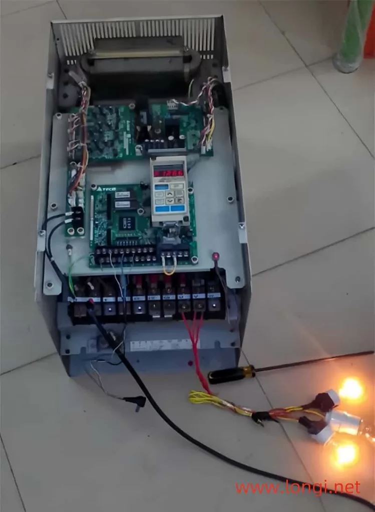
Repair Process and Analysis of a TECO 7200GA-22kW VSD after a Lightning Strike
In the realm of industrial equipment maintenance, dealing with the aftermath of a lightning strike on sensitive electronic devices such as variable speed drives (VSDs) can be particularly challenging. This case study delves into the repair process of a TECO 7200GA-22kW (41kVA) VSD that suffered damage due to a lightning fault. By dissecting the diagnostic steps, repairs, and underlying issues, we aim to provide insights that can aid technicians in similar situations.

Initial Assessment and Repairs
Upon receiving the damaged VSD for repair, the initial inspection revealed that the input rectifier module, switch tube, and shunt tube of the switching power supply had been compromised by the lightning strike. These components were promptly replaced. Following the replacements, the operation panel screen lit up normally, suggesting that the core functionality of the VSD had not been severely impacted.
Subsequent tests on the negative pressure and optocoupler drive input signals for the six channels returned normal results, further reassuring that the repair was progressing positively. However, during the assembly test of the entire unit, an Over Current (OC) fault was triggered immediately upon power-up. Interestingly, the VSD could be reset and started, with the screen displaying normal frequency output values. But during actual testing, no three-phase voltage output was observed at the U, V, and W terminals.
Investigating the Drive Circuit
The local driving ICs employed in the VSD were optocouplers PC923 and PC929, which worked in conjunction with the SN0357 to relay OC signals. An examination of the power amplifier circuit on the output side of the driving ICs and the IGBT tube’s detection circuit revealed no abnormalities. The focus then shifted to the pulse input pin of the PC923 optocoupler, where an anomaly was detected.
Specifically, the level of pin 3 was unexpectedly high while pin 2 was low. This raised the question of whether the driver power supply had been reversed. Normally, in optocoupler circuits, the two pins (anode of the photodiode) are powered by +5V and regulated to provide an excitation power of around 4V, while the third pin (cathode of the photodiode) connects to the pulse output terminal of the CPU. A low-level output is effective, meaning that when the CPU outputs a signal, current is drawn from pin 3 of the PC923, causing the diode to conduct.

Diagnosing the Power Supply Issue
Further investigation revealed that the power supply to pin 2 of the PC923 was a simple series-connected voltage regulator comprising a transistor and a voltage regulator. A faulty base bias resistance in this circuit was identified as the culprit, resulting in a zero supply voltage to pin 2. Replacing the bias resistor restored the voltage levels on pins 2 and 3 of the PC923 to normal. Consequently, upon receiving an operation command, the VSD began outputting voltage from the U, V, and W terminals.
Addressing the OC Fault
With the output issue resolved, attention turned to the persistent OC fault upon power-up. Measurements of the SN0357 optocoupler, responsible for transmitting the OC signal, showed that the voltage value of the two pins on the input side was zero, indicating no OC signal was being input. However, the voltage on the output side of the three optocouplers was 0.5V, which was abnormal. In the absence of an OC signal, the voltage between the two pins should have been 5V (one pin connected to a 5V ground level).
This anomaly pointed to a problem with the 5V pull-up resistance on the signal output pin, which had either changed or become open-circuit. As a result, the CPU erroneously interpreted the situation as receiving an OC signal from the drive circuit, triggering the alarm. Connecting a 10k resistor between the signal output pin and the 5V power supply resolved the issue. Subsequent power-ups showed the signal output pin at 5V, and the OC fault no longer occurred.
Root Cause Analysis
Both faults—the lack of output voltage and the OC fault upon power-up—stemmed from a common issue: power loss. The input pin of the pulse signal and the output pin of the OC signal were directly connected to the CPU pin. When the pull-up high level disappeared, the CPU pin was left with only a low level of 0.5V, insufficient to drive the optocoupler or trigger the inverter module. This low level also led to the detection of OC signals and the jumping of the OC fault code during power-up.
Additional Insights
The motherboards of various Dongyuan VSD series exhibit good replacement characteristics, requiring only the adjustment of the VSD’s capacity value after replacement. This adjustment automatically modifies the relevant parameters for checking the motor’s rated current value. It is worth noting that Dongyuan VSDs’ capacity labeling is often based on kVA rather than kW. For instance, a 22kW capacity is labeled as 41kVA with a rated current of approximately 48A.
The relationship between kW, kVA, and HP values can be confusing for users. In simple terms, 1HP equals 0.75kW, indicating that HP is less than the kW value. kW represents active power, closely approximating the actual power value, while kVA is the apparent power, which includes both active and reactive power components. When selecting a VSD, the kVA value should be chosen based on the rated current value, as it accounts for the reactive power consumption of inductive loads like motors.
Conclusion
This case study underscores the importance of thorough diagnostics and a methodical approach in repairing VSDs damaged by lightning strikes. By understanding the intricacies of the drive circuit, power supply, and signaling mechanisms, technicians can effectively pinpoint and resolve issues, ensuring the reliable operation of industrial equipment. The repair process not only restored the VSD to working condition but also provided valuable insights into the underlying causes of the faults, contributing to a deeper understanding of VSD technology.
