I. Introduction to Operating Panel Functions and Password Settings
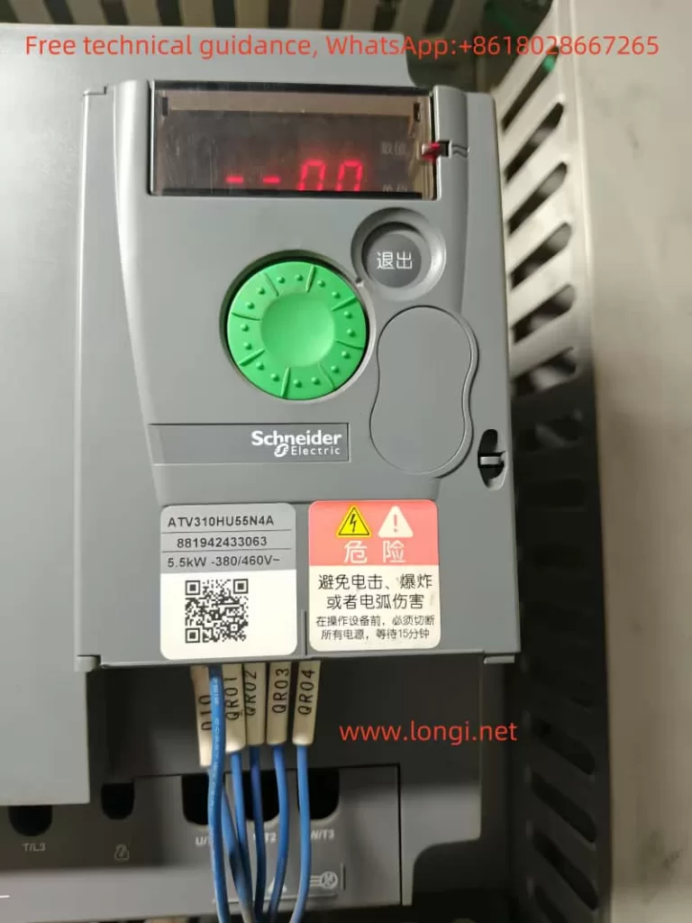
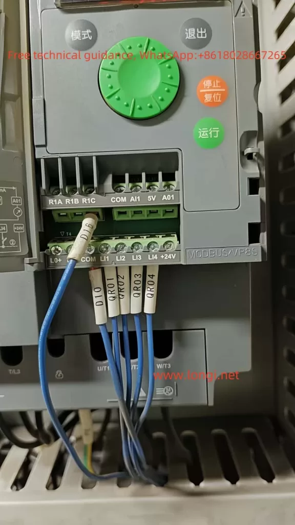
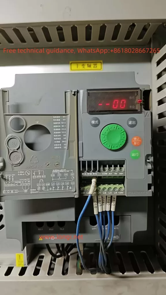
The Schneider ATV310 series of inverters come equipped with an intuitive operating panel that facilitates various settings and operations. The operating panel includes a display screen, multiple buttons, and indicator lights. The display screen shows current parameters and status, while the buttons are used for navigation and parameter setting.

Password Setting and Unlocking
To ensure device security, the ATV310 inverter supports password locking. Users can restrict access to the inverter by setting a password.
- Setting a Password: Enter the “Configuration Mode” (ConF), select the “999 HMI Password” parameter, enter the desired password (ranging from 2 to 9999) using the navigation keys, and press the confirm button to save.
- Unlocking the Inverter: If the inverter is locked, enter the “Configuration Mode”, select the “999 HMI Password” parameter, enter the password, and press the confirm button to unlock. If the password is forgotten, contact Schneider Electric technical support.

Accessing Full Menu Functions and Storing/Restoring Parameters
The ATV310 inverter offers a comprehensive range of parameter settings. Users can access the full menu via the “Configuration Mode” (ConF).
- Accessing the Full Menu: In the “Configuration Mode”, use the navigation keys to select the “FULL” submenu to access the complete list of parameters.
- Storing Parameters: After completing parameter settings, select “101 Store Customer Parameter Settings” and press the confirm button to save the current configuration.
- Restoring Factory Defaults: To reset the inverter to its factory default settings, select “102 Factory/Restore Customer Parameter Settings” and then press the confirm button and select “64”.

II. Setting the External Terminal Operating Mode
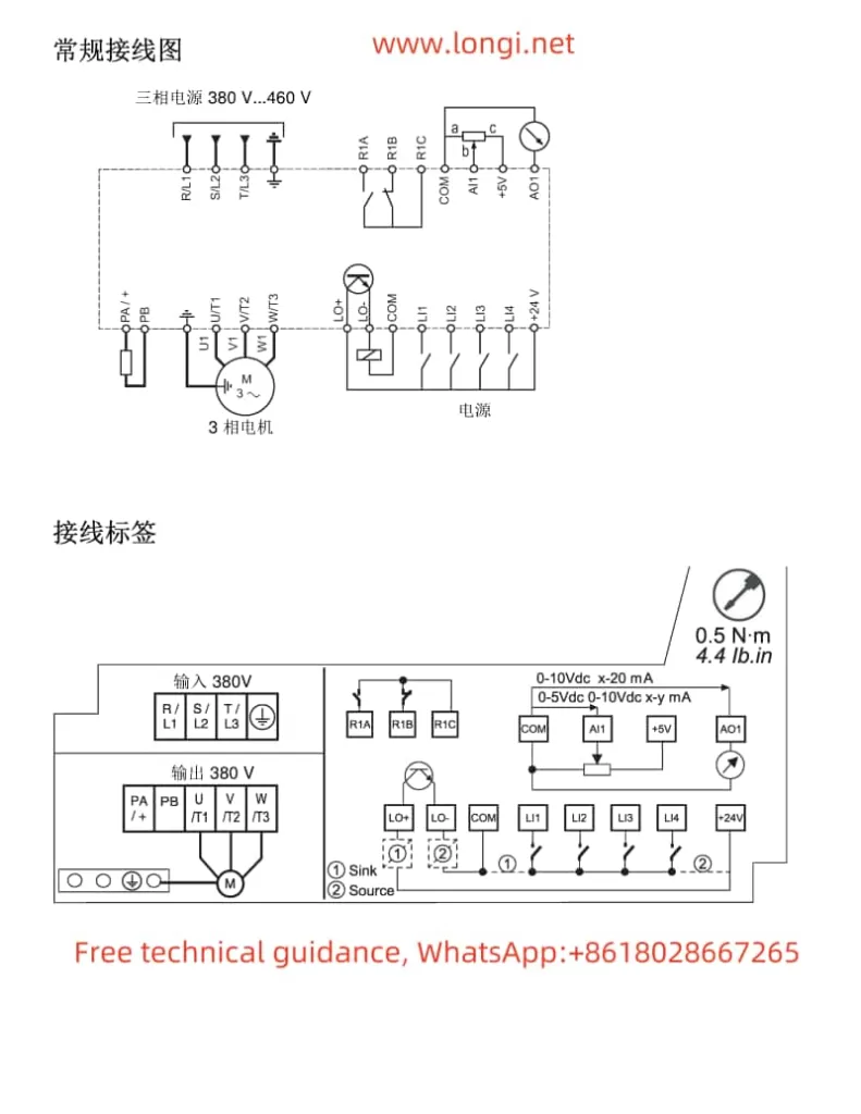
The ATV310 inverter supports the external terminal control mode, allowing users to achieve forward, reverse, high-speed, and low-speed functions through the LI1, LI2, LI3, and LI4 logic input terminals.
Wiring and Parameter Settings
- Wiring:
- Connect the LI1, LI2, LI3, and LI4 terminals to the corresponding outputs of the external controller.
- Ensure all wiring is secure and compliant with safety regulations.
- Parameter Settings:
- Enter the “Configuration Mode” (ConF) and select the “Control Menu” (400-).
- Set the “Control Type” (201) to “3-Wire Control” (01).
- Set the “Logic Input Type” (203) to “Positive Logic” (00) to ensure high-level activation.
- Set the “Given Channel 1” (401) to “Remote Display” (01) to receive speed commands via the external controller.
- Set the “Command Channel 1” (407) to “Terminal” (01) to receive control commands through the LI1-LI4 terminals.
- In the “Input/Output Menu” (200-), assign functions to LI1, LI2, LI3, and LI4:
- LI1: Forward (L1H)
- LI2: Reverse (L2H)
- LI3: High Speed (L3H)
- LI4: Low Speed (L4H)
- In the “Speed Limit Menu” (512-), set the specific frequency values for high speed (512.2) and low speed (512.0).
High and Low Speed Frequency Given
The high and low speed frequencies can be given via the analog or digital outputs of the external controller. If using an analog output, connect the AI1 terminal to the analog output of the external controller and set the AI1 type and range in the “Input/Output Menu” (200-). If using a digital output, directly control high and low speeds through the LI3 and LI4 terminals.

III. Fault Code Analysis and Troubleshooting
The ATV310 inverter features advanced fault diagnosis. When a fault occurs, the corresponding fault code will be displayed on the screen. Users can take appropriate measures based on the code.
Common Fault Codes and Solutions
- F001 Precharge Fault: Possible causes include faulty charging relays or damaged charging resistors. The solution is to check connections, confirm the stability of the main power supply, and contact Schneider Electric technical support if necessary.
- F010 Overcurrent Fault: May be caused by incorrect parameter settings, excessive load, or mechanical lockup. The solution is to check parameter settings, adjust motor/drive/load dimensions, inspect mechanical device status, and connect motor reactors.
- F011 Inverter Overheat Fault: May be caused by excessive load, poor ventilation, or high ambient temperature. The solution is to check motor load, inverter ventilation, and ambient temperature, and wait for the inverter to cool down before restarting.
- F013 Motor Overload Fault: Triggered by excessive motor current. The solution is to check motor thermal protection settings and motor load, and adjust parameters if necessary.
- F014/F015 Output Phase Loss Fault: May be caused by poor motor connections or faulty output contactors. The solution is to check motor connections and output contactor status.
IV. Conclusion
The Schneider ATV310 series inverter user manual provides detailed operating instructions and parameter setting explanations, helping users quickly get started and fully utilize the inverter’s functions. Through this guide, users can understand the operating panel functions, password setting and unlocking methods, steps for setting the external terminal operating mode, and solutions for common fault codes, thereby more effectively using and maintaining the ATV310 inverter. In practical applications, users should set parameters reasonably according to specific needs and environmental conditions, and regularly check the device status to ensure long-term stable operation of the inverter.
