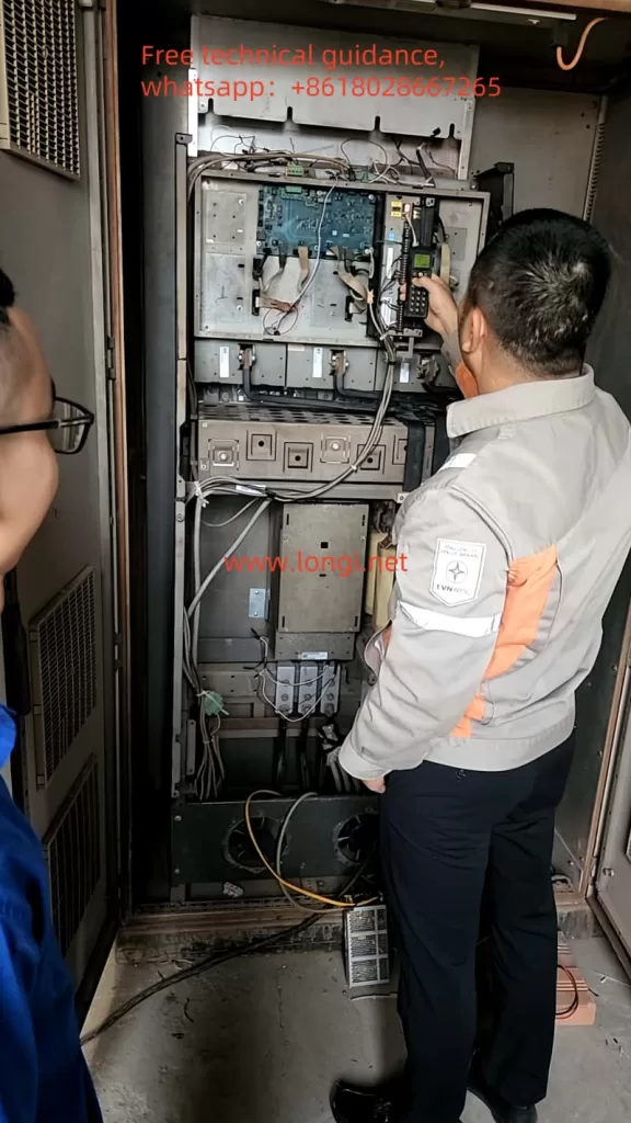
The SEW Servo Drives MDX60B/MDX61B series are widely used in automation control systems, known for their high performance and reliability, meeting the needs of various industrial applications. This guide will provide a detailed introduction to the usage, parameter settings, common faults, and troubleshooting methods of this series, with a focus on explaining the meaning of fault code F196.4 and its resolution.

1. SEW Servo Operation Panel DBG60B Features
The SEW Servo Drives MDX60B/MDX61B series are equipped with the DBG60B operation panel, which provides an easy-to-use interface for monitoring and configuring the drive parameters.
Main Features:
- Operating Status Display: The operation panel can display the current status of the servo drive, including alarms, operating parameters, and other critical information.
- Parameter Settings: Users can set and adjust various parameters to customize the operation of the drive for specific applications.
Setting “Heat Sink Temperature” and “Operating Time”:
- On the DBG60B panel, press the “MENU” button to enter the parameter setting mode.
- Navigate to the “Parameters” menu and find the monitoring options for “Heat Sink Temperature” and “Operating Time.”
- Enable these parameters for display.
- After setting, press the “Confirm” button to save the settings. From then on, the operation panel will show the heat sink temperature and operating time, allowing users to monitor the drive’s operating conditions.
Restoring Factory Default Parameters:
- On the DBG60B panel, press the “MENU” button to enter the parameter setting mode.
- Select “Restore Factory Settings” from the menu.
- Confirm the restoration of factory settings, and the system will reset all parameters to their default values. This is useful for initializing the device or correcting configuration errors.
Setting Password and Locking Parameters:
- In the “Menu” options, select “Password Settings.”
- Enter the default password (usually “0000”), then set a new password.
- Enable “Lock Parameters” to prevent unauthorized modification of critical settings. This step is crucial for preventing accidental changes and ensuring the safety of the equipment.

2. Setting External Terminal Forward/Reverse and External Potentiometer (Analog) for Frequency Control
The SEW Servo MDX60B/MDX61B series supports controlling forward/reverse rotation and adjusting the speed via an external potentiometer or other analog input signals. This is useful for manual speed and direction control in various applications.
Wiring Requirements:
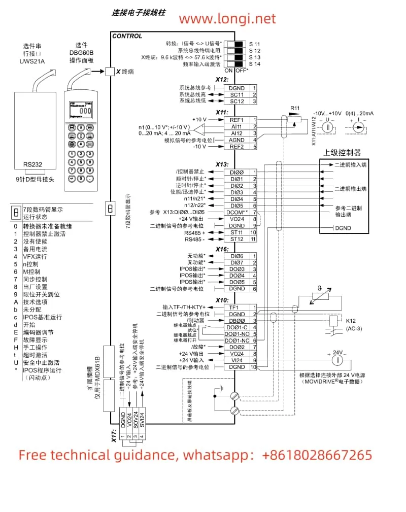
- Forward/Reverse Control: Use digital input terminals (e.g., X10-X12) to connect external pushbuttons or switches for forward and reverse control.
- For example, connect a switch between terminals X10 and X11 to implement forward/reverse control.
- Analog Speed Control via Potentiometer: Use the analog input terminal (e.g., X13) to connect an external potentiometer (10kΩ) or other analog devices that provide a 0-10V or 4-20mA signal to control the speed.
- Terminal X13 is used for the analog input to set the motor speed.
Parameter Settings:
- Setting External Forward/Reverse:
- In the parameter menu, set the “Control Mode” to “External Control.” Map the input terminals X10-X12 to forward/reverse control functions.
- Set the input signal correctly (e.g., X10 for forward, X11 for reverse).
- Setting Analog Potentiometer for Speed Control:
- In the parameters, set the “Speed Control Mode” to “Analog Input Speed Control” and select the appropriate input terminal (e.g., X13).
- Ensure the correct analog signal range (e.g., 0-10V or 4-20mA) is selected to ensure accurate speed control.

3. Common Fault Codes in SEW Servo Drives and Solutions
The SEW Servo MDX60B/MDX61B series may show several common fault codes, including but not limited to:
- F0001 – Overload Protection: This error indicates that the load on the servo motor exceeds its rated capacity, triggering the protection mechanism.
- Solution: Check if the load is too heavy. Adjust the load or reduce the drive output power accordingly.
- F0102 – Motor Overheating: If the motor temperature exceeds the set threshold, this fault is triggered.
- Solution: Check the cooling system, ensure proper airflow, and remove any obstructions that may affect cooling.
- F0203 – Encoder Signal Loss: When the encoder signal is lost or unstable, the drive cannot get accurate position feedback.
- Solution: Inspect the encoder connection, ensuring that the signal wires are intact and not damaged.

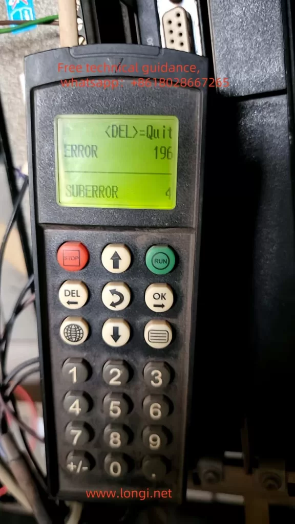
4. Fault F196.4 Meaning and How to Repair It
F196.4 is a fault indicating an issue with the “Inverter Coupling Reference Voltage”, specifically a defective inverter coupling. This fault typically occurs when the reference voltage in the inverter’s coupling circuit is unstable or fails.
F196.4 Fault Analysis:
- Fault Description: The F196.4 fault code generally indicates that the coupling module within the inverter cannot function properly, failing to generate or maintain the required reference voltage. This leads to abnormal signal transmission, affecting the inverter’s operation.
- Possible Causes:
- Failure of the coupling module’s internal power supply, preventing the generation of reference voltage.
- Faulty circuit components (e.g., capacitors, resistors) within the coupling module.
- External power supply issues or unstable voltage leading to abnormal reference voltage.
Solution:
- Check the Coupling Module: Inspect the coupling module for any visible damage or loose connections.
- Measure the Voltage: Use a multimeter or oscilloscope to check the output voltage of the coupling module and ensure it is stable and within the specified range.
- Replace Defective Components: If the coupling module or related components are found to be defective, replace them with the correct parts.
- Verify Power Supply Stability: Ensure the power supply system is stable and the wiring connections are correct.
If the issue persists after these checks, it is recommended to contact SEW-EURODRIVE technical support for further diagnosis and assistance.
Conclusion
The SEW Servo MDX60B/MDX61B series drives, with their high efficiency and versatile functions, are widely used in industrial automation. The DBG60B operation panel provides an intuitive interface for setting parameters, monitoring status, and making adjustments as needed. Understanding common fault codes and their solutions is essential for maintaining system reliability. In particular, F196.4 indicates a serious issue with the inverter’s coupling reference voltage, which requires immediate attention and repair. By following the troubleshooting steps outlined in this guide, users can ensure the smooth operation and longevity of their servo drive systems.
