
The Siemens SINAMICS S120/S150 drive systems are widely used in industrial automation for controlling electric motors. In this guide, we will explore the various features and operations of these systems, covering aspects such as the operation panel, parameter copying, initialization, password settings, parameter access control, and external control connections.
1. Introduction to the Operation Panel (BOP20)
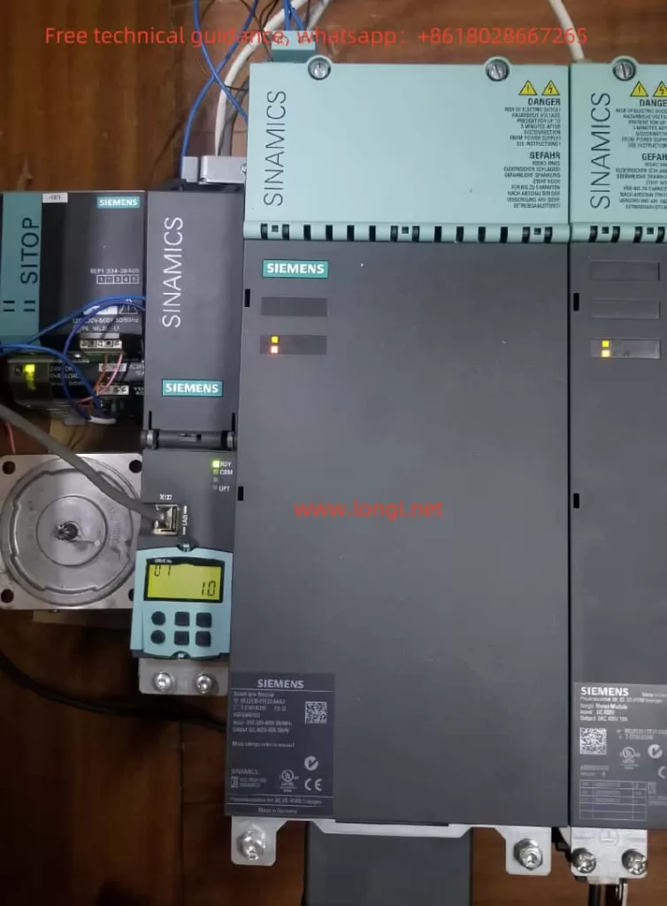
The Basic Operator Panel (BOP20) is an essential interface for the SINAMICS S120 system, offering six buttons and a backlit display for operation. It is designed for simple and efficient interaction with the system, enabling the user to input parameters, display runtime status, and manage errors.
Key Features of BOP20:
- Control and Monitoring: It allows users to input parameters, monitor the system status, and reset faults.
- Access Control: Through the BOP20, users can set the access level, where higher access allows modification of more parameters.
- Error Handling: The panel displays alarms and errors, with options to acknowledge and reset them*2. Copying Parameters Between Drives**
Copying parameters from one drive to another is a common requirement when setting up multiple systems with the same configuration. This can be easily done using the BOP20 or through the expert parameter settings in the STARTER software.
To copy parameters from RAM to ROM:
- Press and hold the “P” button for three seconds, or
- Use parameters like
p0009 = 0andp0977 = 1to initiate the copy .
This sures that all system parameters are consistent across devices and securely saved in non-volatile memory.
3. Parameter Initialization and Factory Reset
For initial setups or after a fault, it may be necessary to perform a full initialization or a factory reset. This can be done either by using the BOP20 or directly through software tools.
To reset the system:
- Set parameter
p0009 = 30to perform a factory reset. - Ensure all components return to their default settings.
This procedure is essential for clearing incorrect configurations or preparing a device for deployment in a different setup.
4. Password Management
To protect the drive system’s settings from unauthorized changes, the S120 allows the user to set a password for configuration access. Passwords can be configured and removed using parameters in the system.
- Setting a Password: Input the desired password through parameter settings in the expert parameter list.
- Removing a Password: The password can be cleared by setting specific parameters (e.g.,
p9761 = 0) .
*5. Par
Access control is crucial for preventing unauthorized changes to system parameters. The S120 system allows for different levels of access, controlled via the BOP20 or the parameter configuration menu. By adjusting the parameter p0003, users can restrict access to certain critical parameters, ensuring that only qualified personnel can modify essential settings .
6. External Control: Forwarrse Rotation, Speed Control via Potentiometer
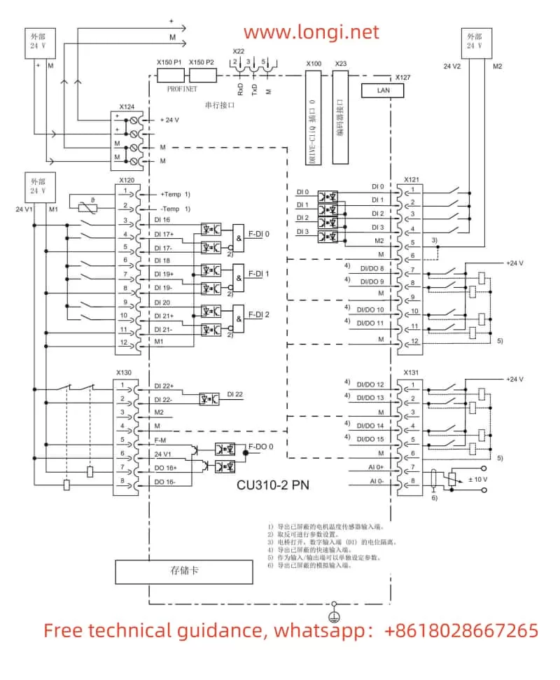
The SINAMICS S120 offers flexible options for integrating external devices, such as external switches and potentiometers, to control motor operations.
- Forward and Reverse Rotation: You can connect external terminals to control the motor’s direction. Specific parameters (
P2589andP2590) are used to define the command source for forward and reverse motion . - Speed Control: For adjusting motor speexternal potentiometer, parameters such as
P2585andP2586can be set to receive and process the analog signals from the potentiometer .
This flexibility ensures that the S120 can be tailorde range of industrial applications, offering both manual and automated control options.
7. Common Fault Codes and Troubleshooting
The S120 system is equipped with an extensive set of diagnostic tools to identify and address issues quickly. Some common fault codes include:
- F01650/F30650: This fault is triggered when the CRC check for Safety Integrated (SI) parameters fails .
- F01680/F30680: This indicates discrepancies in the safettion during operation .
To troubleshoot, ensure that parameters related to Safety Integrated ary configured and that any changes to the system are properly validated through the STARTER or BOP20 interface .
8. Conclusion
The SINAMICS S120 and S150 drives offer advanced feature control, with a user-friendly interface, flexible configuration options, and robust safety and diagnostic features. By understanding the operation panel, copying parameters, initializing settings, and configuring passwords and external control systems, users can ensure optimal performance and secure operation of their industrial automation systems. Additionally, being aware of the fault codes and how to address them will help maintain the system’s reliability and efficiency.
For more advanced configurations and troubleshooting, refer to the SINAMICS S120 Parameter Manual and the related documentation to fully leverage the capabilities of these systems.
This guide incorporates the essential features of the SINAMICS S120 and S150 systems, as outlined in the manuals provided, and addresses user concerns regarding setup, security, control, and fault management.