
In variable frequency water supply control systems, remote pressure gauges play a crucial role in monitoring and maintaining consistent pressure levels. These gauges often exhibit resistance values ranging from 100 to 500 ohms, which correspond to a continuous pressure range, such as 0-10 MPa. Traditionally, this variable resistance can be utilized by series connecting a larger resistor and applying a 0-10V signal. This setup produces a continuously varying voltage that is suitable for frequency converters, PLCs, and other control devices. However, in practical engineering applications, 4-20mA signals are preferred over 0-10V due to their enhanced resistance to interference. Consequently, converting resistance or voltage signals into 4-20mA signals becomes essential for reliable transmission and control.
To address this need, several frequency converter manufacturers have developed specialized water supply signal acquisition boards. These boards are not limited to constant pressure water supply systems and can be applied across various industrial scenarios. Below, we explore three conversion circuits that serve as valuable learning resources and references.
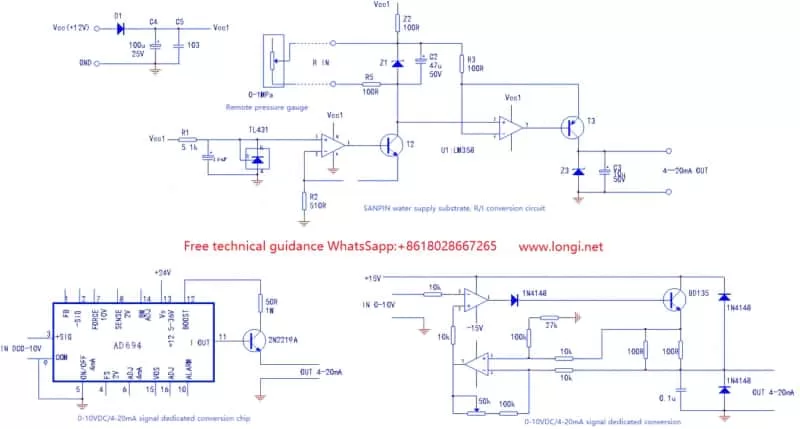
One notable solution is a water supply substrate R/I conversion circuit board designed by a leading frequency converter manufacturer. This board effectively transforms the resistance changes from a remote pressure gauge into a 4-20mA current signal, which is then fed into the control terminal. By comparing this signal with a预设 pressure value, the frequency converter automatically adjusts its output frequency to ensure constant pressure in the water supply network.
The 4-20mA signal source circuit essentially functions as a constant current source with high internal resistance. The output current remains consistent, regardless of the external load resistance. Within this circuit, T2 and T3 form two constant current source circuits: T2 acts as a “fixed” constant current source, while T3 operates as a “variable” one.
The circuit is powered by a 12V DC voltage from the CPU motherboard, which undergoes isolation and filtering through D1 and C4 before reaching the Vcc1 water supply substrate. Further processing by R1 and TL431 converts Vcc1 into a 2.5V reference voltage. This voltage is then used in conjunction with the TL431, operational amplifier circuit (comprising R2, Z2, and the internal resistance of the remote pressure gauge), and the T2 circuit to create a constant current circuit of approximately 4.9 mA.
The resistance changes in the remote pressure gauge are translated into voltage variations across the Z2 resistor. This pressure signal is subsequently input into the second-stage operational amplifier circuit (pins 5 and 6) via R3. The T3 circuit forms the “variable” constant current source, where changes in the gauge’s internal resistance are converted into signal voltage inputs for the operational amplifier. This stage, with deep negative feedback (an amplification factor of 1), maintains a constant current source circuit. The output current is directly dependent on the gauge’s internal resistance.
For enhanced protection, Z1 and Z3 are voltage-embedded protection diodes at the signal input and output terminals. Typically, the internal resistance of the frequency converter’s current input terminals is 250 ohms.
Alternatively, dedicated signal conversion chips, such as the AD694, simplify the conversion process. These chips require only a current-limiting resistor and a transistor to accurately convert 0-10V signals to 4-20mA. With the control terminal of the frequency converter powered by a 24V supply, these chips offer excellent anti-interference performance.
A third option involves constructing a 0-10V/4-20mA signal conversion circuit using an operational amplifier circuit and discrete components. However, this approach necessitates two power supplies and initial output current adjustments, making it less practical and less commonly used.
In conclusion, converting 0-10VDC to 4-20mA signals is crucial for ensuring robust and interference-resistant transmission in water supply control systems. The described circuits and solutions provide effective means of achieving this conversion, catering to various industrial applications and requirements.