
The SINCR C6000 series is a high-performance variable frequency drive widely used in industrial automation, mechanical processing, petrochemical, and other fields. This article provides a detailed introduction to the operation panel functions, parameter settings, fault resolution, and more for the SINCR C6000 series variable frequency drive, helping users better operate and maintain the device.
I. Operation Panel Function Introduction
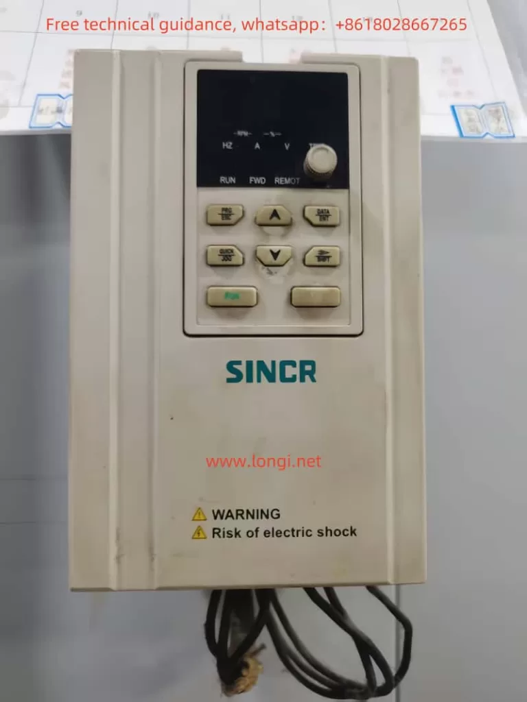
1. Operation Panel Functions
The operation panel of the SINCR C6000 series variable frequency drive is the primary interface for user interaction, integrating functions such as operation control, parameter settings, and display. The panel features eight buttons with the following functions:
- PRG/PRG: Program key, used to enter or exit the function code editing mode.
- DATA/ENT: Enter the next menu or confirm data.
- A: Increment data.
- V: Decrement data.
- SHIFT: Shift key, used to select data bits or cycle through display parameters.
- RUN: Run key, used to start or stop the variable frequency drive.
- STOP/RST: Stop/Reset key, used to stop operation or reset faults.
- QUICK/JOG: Inching key, press and hold for inching operation, release to return to the previous state.
2. How to Copy Parameters to Another Variable Frequency Drive
The SINCR C6000 series supports parameter copying, allowing users to copy the parameter settings from one variable frequency drive to another. The specific steps are as follows:
- Enter the parameter setting interface by pressing the PRG key, select function code F0.18, and set it to 1 (restore factory settings).
- Export the parameters to a storage device (such as a USB drive), following the specific method in the variable frequency drive operation manual.
- Insert the storage device into the target variable frequency drive, enter the parameter setting interface, select the parameter import function, and import the parameters into the target variable frequency drive.
- After completing the parameter import, press the PRG key to exit the parameter setting interface.
3. How to Restore Parameter Initialization Settings
When the variable frequency drive encounters a fault or needs to be reconfigured, the parameter initialization settings can be restored. The specific steps are as follows:
- Press the PRG key to enter the function code editing mode.
- Select function code F0.18 and set it to 1 (restore factory settings).
- Press the ENT key to confirm the restoration of factory settings.
- The variable frequency drive will automatically restore to the factory settings. After completion, press the PRG key to exit.
4. How to Set and Remove Passwords
To prevent unauthorized personnel from operating the variable frequency drive, a password protection feature can be set. The specific steps are as follows:
- Press the PRG key to enter the function code editing mode.
- Select function code F7.00 and enter a password (range: 0~65535).
- Press the ENT key to confirm the password setting.
To remove the password, follow these steps:
- Press the PRG key to enter the function code editing mode.
- Select function code F7.00 and set the password to 0.
- Press the ENT key to confirm the removal of the password.
5. How to Set Parameter Access Restrictions
To prevent unauthorized personnel from modifying the variable frequency drive parameters, parameter access restrictions can be set. The specific steps are as follows:
- Press the PRG key to enter the function code editing mode.
- Select function code F7.00 and enter a password (range: 0~65535).
- Press the ENT key to confirm the password setting.
- After setting, the variable frequency drive will require a password to enter the parameter setting interface.
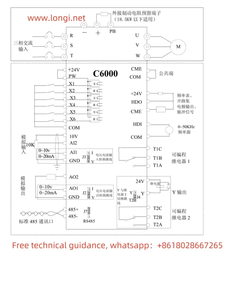
II. External Terminal Control and Speed Adjustment
1. External Terminal Forward and Reverse Control
The SINCR C6000 series supports forward and reverse control through external terminals. The specific wiring and parameter settings are as follows:
Wiring:
- X1 Terminal: Forward control, connect to run forward, disconnect to stop.
- X2 Terminal: Reverse control, connect to run reverse, disconnect to stop.
Parameter Settings:
- Press the PRG key to enter the function code editing mode.
- Select function code F5.01 and set it to 1 (forward operation).
- Select function code F5.02 and set it to 2 (reverse operation).
- Press the ENT key to confirm the parameter settings.
2. External Potentiometer Speed Adjustment
The SINCR C6000 series supports speed adjustment through an external potentiometer. The specific wiring and parameter settings are as follows:
Wiring:
- AI1 Terminal: Analog input terminal, connect to the output signal of the external potentiometer.
Parameter Settings:
- Press the PRG key to enter the function code editing mode.
- Select function code F0.02 and set it to 1 (analog AI1 setting).
- Select function code F5.09 and set the lower limit value for the AI1 terminal (range: 0.00V~10.00V).
- Select function code F5.10 and set the lower limit corresponding to the AI1 terminal setting (range: -100.0%~100.0%).
- Select function code F5.11 and set the upper limit value for the AI1 terminal (range: 0.00V~10.00V).
- Select function code F5.12 and set the upper limit corresponding to the AI1 terminal setting (range: -100.0%~100.0%).
- Press the ENT key to confirm the parameter settings.
III. Fault Codes and Solutions
The SINCR C6000 series variable frequency drive may encounter various faults during operation, which are indicated by fault codes. Below are common fault codes, their meanings, and solutions:
1. Fault Codes and Meanings
- Err01: Inverter unit U phase protection.
- Err02: Inverter unit V phase protection.
- Err03: Inverter unit W phase protection.
- Err04: Acceleration overcurrent.
- Err05: Deceleration overcurrent.
- Err06: Constant speed overcurrent.
- Err07: Acceleration overvoltage.
- Err08: Deceleration overvoltage.
- Err09: Constant speed overvoltage.
- Err10: Bus undervoltage fault.
- Err11: Motor overload.
- Err12: Variable frequency drive overload.
- Err13: Input phase loss.
- Err14: Output phase loss.
- Err15: Rectifier block overheating.
- Err16: Inverter module overheating fault.
- Err17: External fault.
- Err18: Communication fault.
- Err19: Current detection fault.
- Err20: Motor self-learning fault.
- Err21: EEPROM operation fault.
- Err22: PID feedback disconnection fault.
- Err23: Braking unit fault.
2. Fault Solutions
Err01~Err03 (Inverter Unit Protection):
- Cause: Overheating or short circuit in the inverter unit.
- Solution: Check the heat dissipation of the inverter unit, ensure the fan is working properly; check the wiring of the inverter unit, and eliminate short circuit faults.
Err04~Err06 (Overcurrent Protection):
- Cause: Motor overload or excessive output current from the variable frequency drive.
- Solution: Reduce the motor load; check the parameter settings of the variable frequency drive to ensure the motor parameters match the variable frequency drive.
Err07~Err09 (Overvoltage Protection):
- Cause: Input voltage is too high or parameter settings are incorrect.
- Solution: Check if the input voltage is within the rated range of the variable frequency drive; adjust the parameter settings to ensure the output voltage is within a reasonable range.
Err10 (Bus Undervoltage Fault):
- Cause: Input voltage is too low.
- Solution: Check if the input voltage is within the rated range of the variable frequency drive; ensure the input power supply is stable.
Err11 (Motor Overload):
- Cause: Motor load is too high.
- Solution: Reduce the motor load; check if the motor parameters match the variable frequency drive.
Err12 (Variable Frequency Drive Overload):
- Cause: Excessive output current from the variable frequency drive.
- Solution: Reduce the motor load; check the parameter settings of the variable frequency drive to ensure the motor parameters match the variable frequency drive.
Err13~Err14 (Phase Loss Protection):
- Cause: Phase loss in the input or output power supply.
- Solution: Check the wiring of the input or output power supply; ensure the power supply is normal.
Err15~Err16 (Overheating Protection):
- Cause: Overheating of the rectifier block or inverter module.
- Solution: Check if the cooling fan is working properly; ensure the heat dissipation path of the variable frequency drive is unobstructed.
Err17 (External Fault):
- Cause: Fault in external equipment.
- Solution: Check the wiring and operation status of the external equipment, and eliminate external faults.
Err18 (Communication Fault):
- Cause: Communication line fault or incorrect communication parameter settings.
- Solution: Check if the communication line is normal; adjust the communication parameter settings to ensure normal communication.
Err19 (Current Detection Fault):
- Cause: Current sensor fault.
- Solution: Check the wiring and operation status of the current sensor, and eliminate sensor faults.
Err20 (Motor Self-Learning Fault):
- Cause: Motor parameter self-learning failure.
- Solution: Check if the motor parameter settings are correct; perform motor parameter self-learning again.
Err21 (EEPROM Operation Fault):
- Cause: EEPROM memory fault.
- Solution: Replace the EEPROM memory.
Err22 (PID Feedback Disconnection Fault):
- Cause: PID feedback line disconnection.
- Solution: Check the wiring and operation status of the PID feedback line, and eliminate disconnection faults.
Err23 (Braking Unit Fault):
- Cause: Braking unit fault.
- Solution: Check the wiring and operation status of the braking unit, and eliminate braking unit faults.
Conclusion
The SINCR C6000 series is a powerful and easy-to-operate variable frequency drive. Through reasonable parameter settings and correct operation, precise control and efficient speed adjustment of the motor can be achieved. This article provides a detailed introduction to the operation panel functions, parameter settings, and fault resolution of the variable frequency drive, aiming to help users better operate and maintain the device. If problems are encountered during use, it is recommended to refer to the variable frequency drive user manual or contact the manufacturer’s technical support to ensure the normal operation and long-term stability of the device.