
The control characteristics of ABB VFD ACS510 for water supply are as follows:
- High control precision and good stability: It provides powerful support for the automatic control of constant pressure water supply systems by achieving precise speed regulation, reduced starting current, power saving, high reliability, and jitter control.
- Simple design and easy operation: It adopts a visual interface design and an easy-to-operate keyboard controller. Through the intuitive operating interface, users can easily understand the working status of the VFD and more easily guide and maintain it.
- High reliability and strong safety: It has multiple protection functions such as overcurrent, overvoltage, and short circuit, and reduces mechanical vibration and noise of the motor, thereby reducing the maintenance cost of the motor and the safety risks for users.
- Perfect matching with fans and pumps: The enhanced PFC application can control up to 7 (1+6) water pumps and switch more pumps. The SPFC cyclic soft start function can adjust each pump sequentially, with a maximum of 6 water pumps, without the need for an additional PLC.
- Improving the safety of the system: The constant pressure frequency conversion water supply using ABB ACS510 improves the safety of equipment operation. The water supply system, with PLCs and VFDs, has stable and efficient intelligent integrated circuits with automatic detection, leakage protection, phase failure protection, and automatic alarm functions.
- Improving the performance of water supply systems: In the centrifugal pump parallel operation mode of water supply, if one of the centrifugal pumps fails, the thermal relay controlling this centrifugal pump can be set to failure. At this time, the corresponding frequency control cabinet will display that this centrifugal pump has failed, the fault light will turn on, and when the frequency conversion water supply system is running, it will skip the operation of the centrifugal pump and motor with the failure, improving the performance of water supply systems.
In summary, ABB VFD ACS510 has characteristics such as high precision, good stability, simple design, high reliability, strong safety, etc., improving the performance and safety of water supply systems.
One-to-one PID configuration:
ABB VFD one-to-one wiring
The one-to-one PID configuration is typically used to control a target variable, such as temperature, pressure, or flow rate, and regulate the output of the VFD using an input signal. For the one-to-one wiring of the ABB VFD, the following steps can be followed:
Determine the required input and output signals: A control signal input (such as analog input AI or digital input DI) is typically required to receive the control signal, and an output signal (such as analog output AO or digital output DO) is used to control the output frequency of the VFD.
Connect the input signal: Attach the control signal wire to the corresponding input terminals on the VFD. If using analog input, ensure that the resistance and potentiometer on the signal wire are set correctly. If using digital input, connect the signal wire to the corresponding DI terminals.
Connect the output signal: Attach the output frequency wire from the VFD to the corresponding output terminals. If using analog output, ensure that the resistance and potentiometer on the signal wire are set correctly. If using digital output, connect the signal wire to the corresponding DO terminals.
Set the VFD parameters: Configure the VFD parameters according to the control requirements. This includes setting the target frequency, maximum and minimum frequencies, acceleration time, and deceleration time, among others.
Debug and test: After completing the wiring and parameter settings, perform testing to ensure that the system is functioning properly. Check that the input signal is correctly controlling the output of the VFD and that the system is stable and operating under various conditions.
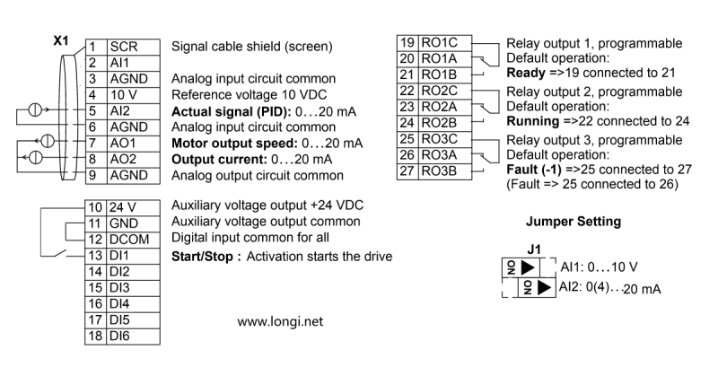
Actual wiring instructions for a one-to-one scenario
- 1.For voltage output instruments, such as a remote pressure gauge (range 0-10V), connect the three wires to terminals 4, 5, and 6 according to the labeling (internal resistance requirements: 1KΩ-10KΩ). Simultaneously, move the AI2 DIP switch in jumper J1 on the terminal block to the left (as shown in the diagram above). This signal represents the actual pressure feedback value.
If it’s a current output pressure sensor, connect the two wires to terminals 5 and 6. Simultaneously, move the AI2 DIP switch in jumper J1 on the terminal block to the right (as shown in the diagram above). - 2.Short-circuit terminals 11 and 12.
- 3.Connecting terminals 10 and 13 provides the start signal.
Parameter Settings:
99.02 6 = PID Control Macro
This parameter sets the control macro to PID, which means the device will use Proportional-Integral-Derivative control for precise regulation.
10.02 1 = DI1 Controls Start/Stop
This setting determines that Digital Input 1 (DI1) will be used to control the starting and stopping of the process or device.
11.02 7 = External 2
This parameter is likely referring to an external control source or input selection. “External 2” could be a specific configuration for an external signal or device.
13.04 20% (When the actual signal is 4-20mA or 2-10V)
This setting configures the input signal scaling. It indicates that when the incoming signal is within the range of 4-20mA or 2-10V, it will be interpreted as 20% of the full scale value.
16.01 0 – No start permissive signal required
This parameter indicates that no external permissive signal is needed to start the device or process. It’s set to 0, which means the start permissive signal is not required.
40.10 19 (Internal setpoint)
This parameter sets the internal setpoint to 19. The exact meaning of this value depends on the context and scaling of the system, but it typically represents a target value for the controlled variable.
40.11 Set pressure value (Percentage of the pressure gauge range, e.g., if the target is 8 kg and the range is 16 kg, set it to 50%)
This parameter is used to set the desired pressure as a percentage of the pressure gauge’s total range. In the example given, the target pressure is 8 kg out of a possible 16 kg range, so it’s set to 50%.
ABB Drives ACS510 One-to-Three Wiring
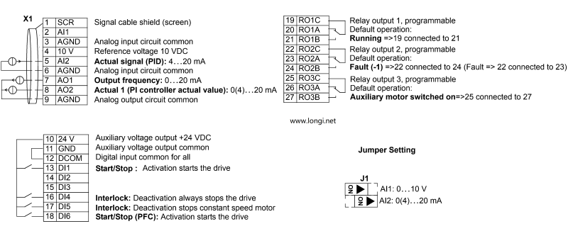
1.The feedback signal from the pressure sensor is of the current type. To align with this, configure J1 for current input by dialing the code to the right.
2.Establish a short circuit between pins 11 and 12.
3.Connecting pins 10 and 13 initiates the start signal.
4.For the interlocked startup of three pumps, establish connections between pin 10 and pins 16, 17, and 18 respectively.
5.Each of the three pumps should be wired to a separate relay, ensuring individual control.
VFD Parameter Settings
Parameter Set Value
99.02 6 = PID Control Macro
10.02 1 = DI1 Controls Start/Stop
11.02 7 = External 2
13.04 20% (When the actual signal is 4-20mA or 2-10V)
14.01 31 = PFC Control
14.02 31 = PFC Control
14.03 31 = PFC Control
16.01 0 – No start permissive signal required
40.10 19 (Internal setpoint)
40.11 Set pressure value (Percentage of the pressure gauge range, e.g., if the target is 8 kg and the range is 16 kg, set it to 50%)
81.17 2 = Number of auxiliary units
81.27 3 = Number of auxiliary units
Note: There seems to be a redundancy in the parameters 14.01, 14.02, and 14.03, all set to “PFC Control” and parameters 81.17 and 81.27 both referring to “Number of auxiliary units”. Please check if these are indeed distinct parameters or if some correction is needed. Additionally, ensure that the parameter names and values align with the specific model and manual of the frequency converter being used.