
I. Operating Panel (Control Pad) Usage
1. Overview of Control Pad
The operating panel (control pad) of the ACH550 inverter serves as the primary interface between the user and the inverter, enabling status display, parameter setting, and operation control.
2. Basic Operations
- Starting and Stopping:
- Press “HAND” Button: Enters manual mode, allowing adjustment of inverter output frequency via the up and down arrow keys.
- Press “AUTO” Button: Switches to automatic mode, where inverter operation is controlled by external signals (such as terminal signals or communication signals).
- Display Mode Switching:
- Access different display modes (e.g., output mode, parameter mode, assistant mode) through the menu button (MENU) on the control pad.
- Parameter Setting:
- In parameter mode, use the up and down arrow keys to select the parameter to modify. Press the edit button (EDIT) to enter the parameter settings, input new values using the numeric keys, and save changes with the save button (SAVE).
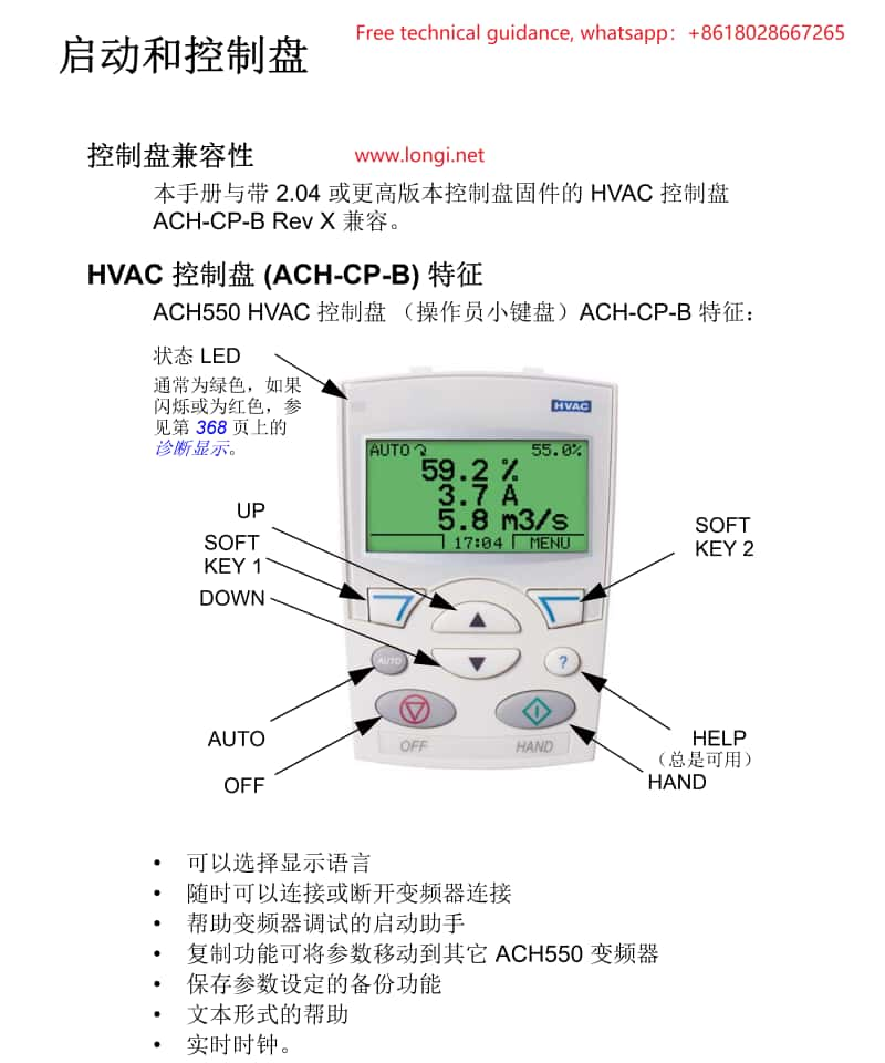
3. Assistant Mode
The assistant mode provides guided steps for starting and configuring the inverter, ideal for first-time users or those requiring quick setup.
II. Terminal Starting and Potentiometer Speed Control
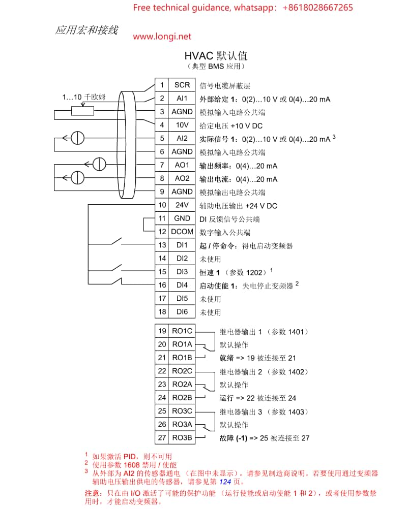
1. Terminal Starting Wiring
- Connect Main Power: Wire the inverter’s input power to the corresponding terminals (U1, V1, W1).
- Connect Motor: Connect motor wires to the inverter’s output terminals (U2, V2, W2).
- Control Signal Wiring:
- Connect the start signal (e.g., DI1) to the inverter’s digital input terminal.
- If direction control is required, connect the direction signal to the corresponding terminal (e.g., DI2).
2. Potentiometer Speed Control Wiring
- Potentiometer Selection: Choose an appropriate rotary or slide potentiometer.
- Wiring:
- Connect the three pins of the potentiometer to the inverter’s analog input terminals (e.g., positive, negative, and signal terminals of AI1).
- Adjust the potentiometer knob to vary the voltage or current signal input to AI1, thereby controlling the inverter’s output frequency.
3. Parameter Setting
- Enter parameter mode and select an appropriate macro (e.g., fan macro or general PID macro) that presets parameters suitable for specific applications.
- Adjust parameters related to start/stop, direction control, and analog inputs based on actual wiring configurations.
III. Inverter Fault Code Analysis and Troubleshooting
1. Fault Code Inquiry
Display recent fault codes through the control pad, which correspond to different fault types.
2. Common Fault Codes and Troubleshooting Methods
- Overcurrent Fault:
- Cause: Motor overload, motor short circuit, improper parameter settings, etc.
- Solution: Check motor and load conditions, adjust overload protection parameters, and confirm inverter and motor parameter compatibility.
- Undervoltage Fault:
- Cause: Low or fluctuating input power voltage.
- Solution: Verify power supply voltage stability, increase input filter capacitors, or adjust undervoltage protection thresholds.
- Overheat Fault:
- Cause: Poor inverter cooling, high ambient temperature.
- Solution: Improve inverter cooling conditions, such as installing additional cooling fans or reducing ambient temperature.
- Communication Fault:
- Cause: Communication line issues, incorrect communication parameter settings.
- Solution: Check communication line connections, ensure communication parameter settings match the device configuration.
IV. Precautions
- Always disconnect inverter power before performing any wiring or parameter adjustments.
- Observe control pad status indicators and fault codes during operation, promptly addressing potential issues.
- For complex faults or unsolvable problems, contact ABB technical support or a qualified service