Posted on Leave a comment

ACS510 Variable Frequency Drive (VFD) User Guide: Operating Panel Usage, Terminal Mode Startup and Speed Adjustment Methods, Fault Analysis and Solution Methods

ACS510 Variable Frequency Drive (VFD) User Guide

I. Operating Panel Usage

  1. Power On/Off
    Before powering on, ensure all connections are correct and the surrounding environment meets safety standards.
    Use the power switch on the operating panel to turn the power on or off.
  2. Mode Switching
    LOC/REM Button: Used to switch the control mode of the VFD. Press and hold this button for 2 seconds to toggle between Local Control (LOC) and Remote Control (REM) modes.
    In Remote Control mode, the VFD can be controlled via external terminals or communication interfaces.
  3. Display and Operation
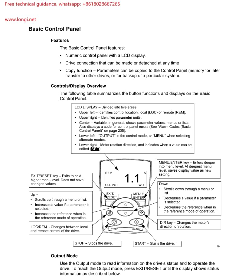
    Display: The LCD screen on the operating panel displays various status information of the VFD, such as motor speed, current, voltage, etc.
    Button Operation: Use the Up/Down arrow buttons to navigate through menus and parameters. The MENU/ENTER button is used to enter and exit menus, while the EXIT/RESET button exits to the previous menu level or resets settings.
  4. Parameter Modification
    Enter the parameter mode, select the parameter group to be modified, adjust the parameter value using the Up/Down arrow buttons, and save the settings with the SAVE button.
ACS510 drive operation panel basic function diagram

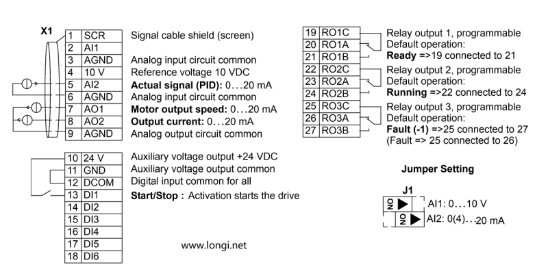
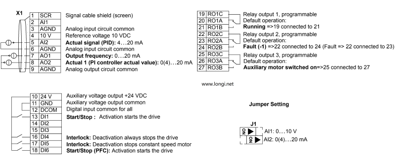
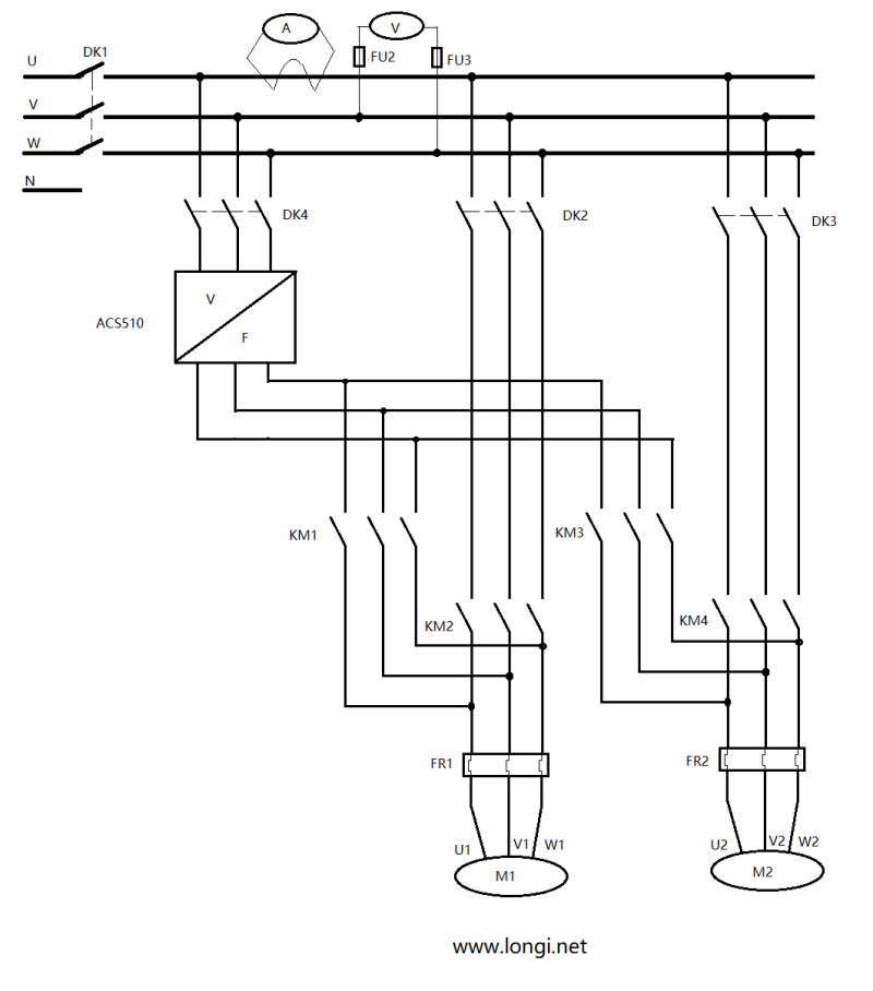
II. VFD Terminal Start-up and Potentiometer Speed Control Wiring Methods

  1. Terminal Start-up Wiring
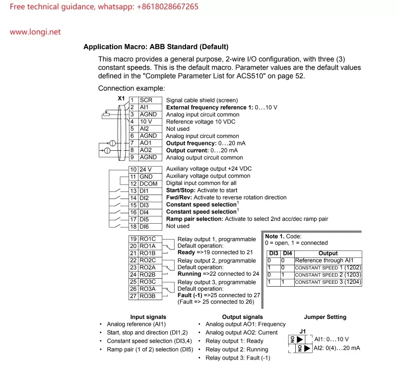
    External Start Signal: Typically, connect the external start signal (e.g., a push-button switch) to the DI1 (Digital Input 1) terminal of the VFD and connect the common terminal to DI COM (Digital Input Common).
    Direction Control: If direction control is required, connect the direction signal to the DI2 terminal.
    Run Enable: Some applications may require an additional run enable signal, which can be connected to the appropriate DI terminal.
  2. Potentiometer Speed Control Wiring
    Analog Input Wiring: When using a potentiometer for speed control, connect the output terminal of the potentiometer to the AI1 (Analog Input 1) terminal of the VFD and connect AI COM (Analog Input Common) to the common terminal.
    Parameter Setting: In parameter group 11, set Reference 1 Select (REF1 SELECT) to AI1 to ensure the VFD receives the speed reference signal from AI1.
standard macro of ACS510 drive function diagram

III. Parameter Settings

  1. Selecting Standard Macros
    Enter parameter group 99, find parameter 9902 (APPLIC MACRO), set it to 1, and select the ABB standard macro. This will automatically set a predefined set of parameters suitable for most general applications.
  2. Motor Parameter Settings
    Input the motor’s rated voltage (9905 MOTOR NOM VOLT), rated current (9906 MOTOR NOM CURR), rated frequency (9907 MOTOR NOM FREQ), rated speed (9908 MOTOR NOM SPEED), and rated power (9909 MOTOR NOM POWER), ensuring these parameters match the data on the motor’s nameplate.
  3. Other Important Parameters
    Acceleration Time (2202 ACCELER TIME 1): Sets the time required for the motor to accelerate from rest to maximum frequency.
    Deceleration Time (2203 DECELER TIME 1): Sets the time required for the motor to decelerate from maximum frequency to rest.
    Maximum Output Frequency (2008 MAXIMUM FREQ): Sets the maximum frequency output of the VFD.

IV. VFD Fault Code Analysis and Resolution Methods

  1. Overcurrent Fault (Code 1: OVERCURRENT)
    Cause: Motor overload, excessively short acceleration time, motor fault, etc.
    Solution: Check if the motor is overloaded, increase the acceleration time, inspect motor and cable connections.
  2. DC Overvoltage (Code 2: DC OVERVOLT)
    Cause: Excessively high input voltage, excessively short deceleration time, improper braking resistor, etc.
    Solution: Check the input voltage, increase the deceleration time, inspect the braking resistor configuration.
  3. Overtemperature Fault (Code 3: DEV OVERTEMP)
    Cause: Excessively high ambient temperature, faulty cooling fan, dust accumulation, etc.
    Solution: Lower the ambient temperature, clean dust, replace faulty fan.
  4. Motor Stall (Code 12: MOTOR STALL)
    Cause: Motor or load stall, improper motor selection, etc.
    Solution: Inspect the motor and load, ensure correct motor selection.
  5. Panel Loss (Code 10: PANEL LOSS)
    Cause: Communication fault between the control panel and the VFD.
    Solution: Check control panel connections, communication settings, and cables.

Please follow this guide for operation and adjust parameters and wiring according to actual conditions. If any issues arise, please contact us technical support promptly.

Posted on Leave a comment

The characteristics, usage methods, parameter settings, and wiring of ABB drive ACS510 constant pressure water supply control

The control characteristics of ABB VFD ACS510 for water supply are as follows:

  1. High control precision and good stability: It provides powerful support for the automatic control of constant pressure water supply systems by achieving precise speed regulation, reduced starting current, power saving, high reliability, and jitter control.
  2. Simple design and easy operation: It adopts a visual interface design and an easy-to-operate keyboard controller. Through the intuitive operating interface, users can easily understand the working status of the VFD and more easily guide and maintain it.
  3. High reliability and strong safety: It has multiple protection functions such as overcurrent, overvoltage, and short circuit, and reduces mechanical vibration and noise of the motor, thereby reducing the maintenance cost of the motor and the safety risks for users.
  4. Perfect matching with fans and pumps: The enhanced PFC application can control up to 7 (1+6) water pumps and switch more pumps. The SPFC cyclic soft start function can adjust each pump sequentially, with a maximum of 6 water pumps, without the need for an additional PLC.
  5. Improving the safety of the system: The constant pressure frequency conversion water supply using ABB ACS510 improves the safety of equipment operation. The water supply system, with PLCs and VFDs, has stable and efficient intelligent integrated circuits with automatic detection, leakage protection, phase failure protection, and automatic alarm functions.
  6. Improving the performance of water supply systems: In the centrifugal pump parallel operation mode of water supply, if one of the centrifugal pumps fails, the thermal relay controlling this centrifugal pump can be set to failure. At this time, the corresponding frequency control cabinet will display that this centrifugal pump has failed, the fault light will turn on, and when the frequency conversion water supply system is running, it will skip the operation of the centrifugal pump and motor with the failure, improving the performance of water supply systems.

In summary, ABB VFD ACS510 has characteristics such as high precision, good stability, simple design, high reliability, strong safety, etc., improving the performance and safety of water supply systems.

One-to-one PID configuration:

ABB VFD one-to-one wiring
The one-to-one PID configuration is typically used to control a target variable, such as temperature, pressure, or flow rate, and regulate the output of the VFD using an input signal. For the one-to-one wiring of the ABB VFD, the following steps can be followed:

Determine the required input and output signals: A control signal input (such as analog input AI or digital input DI) is typically required to receive the control signal, and an output signal (such as analog output AO or digital output DO) is used to control the output frequency of the VFD.

Connect the input signal: Attach the control signal wire to the corresponding input terminals on the VFD. If using analog input, ensure that the resistance and potentiometer on the signal wire are set correctly. If using digital input, connect the signal wire to the corresponding DI terminals.

Connect the output signal: Attach the output frequency wire from the VFD to the corresponding output terminals. If using analog output, ensure that the resistance and potentiometer on the signal wire are set correctly. If using digital output, connect the signal wire to the corresponding DO terminals.

Set the VFD parameters: Configure the VFD parameters according to the control requirements. This includes setting the target frequency, maximum and minimum frequencies, acceleration time, and deceleration time, among others.

Debug and test: After completing the wiring and parameter settings, perform testing to ensure that the system is functioning properly. Check that the input signal is correctly controlling the output of the VFD and that the system is stable and operating under various conditions.

Actual wiring instructions for a one-to-one scenario

  1. 1.For voltage output instruments, such as a remote pressure gauge (range 0-10V), connect the three wires to terminals 4, 5, and 6 according to the labeling (internal resistance requirements: 1KΩ-10KΩ). Simultaneously, move the AI2 DIP switch in jumper J1 on the terminal block to the left (as shown in the diagram above). This signal represents the actual pressure feedback value.
    If it’s a current output pressure sensor, connect the two wires to terminals 5 and 6. Simultaneously, move the AI2 DIP switch in jumper J1 on the terminal block to the right (as shown in the diagram above).
  2. 2.Short-circuit terminals 11 and 12.
  3. 3.Connecting terminals 10 and 13 provides the start signal.

Parameter Settings:

99.02 6 = PID Control Macro
This parameter sets the control macro to PID, which means the device will use Proportional-Integral-Derivative control for precise regulation.

10.02 1 = DI1 Controls Start/Stop
This setting determines that Digital Input 1 (DI1) will be used to control the starting and stopping of the process or device.

11.02 7 = External 2
This parameter is likely referring to an external control source or input selection. “External 2” could be a specific configuration for an external signal or device.

13.04 20% (When the actual signal is 4-20mA or 2-10V)
This setting configures the input signal scaling. It indicates that when the incoming signal is within the range of 4-20mA or 2-10V, it will be interpreted as 20% of the full scale value.

16.01 0 – No start permissive signal required
This parameter indicates that no external permissive signal is needed to start the device or process. It’s set to 0, which means the start permissive signal is not required.

40.10 19 (Internal setpoint)
This parameter sets the internal setpoint to 19. The exact meaning of this value depends on the context and scaling of the system, but it typically represents a target value for the controlled variable.

40.11 Set pressure value (Percentage of the pressure gauge range, e.g., if the target is 8 kg and the range is 16 kg, set it to 50%)
This parameter is used to set the desired pressure as a percentage of the pressure gauge’s total range. In the example given, the target pressure is 8 kg out of a possible 16 kg range, so it’s set to 50%.

ABB Drives ACS510 One-to-Three Wiring

1.The feedback signal from the pressure sensor is of the current type. To align with this, configure J1 for current input by dialing the code to the right.

2.Establish a short circuit between pins 11 and 12.

3.Connecting pins 10 and 13 initiates the start signal.

4.For the interlocked startup of three pumps, establish connections between pin 10 and pins 16, 17, and 18 respectively.

5.Each of the three pumps should be wired to a separate relay, ensuring individual control.

VFD Parameter Settings

Parameter Set Value

99.02 6 = PID Control Macro

10.02 1 = DI1 Controls Start/Stop

11.02 7 = External 2

13.04 20% (When the actual signal is 4-20mA or 2-10V)

14.01 31 = PFC Control

14.02 31 = PFC Control

14.03 31 = PFC Control

16.01 0 – No start permissive signal required

40.10 19 (Internal setpoint)

40.11 Set pressure value (Percentage of the pressure gauge range, e.g., if the target is 8 kg and the range is 16 kg, set it to 50%)

81.17 2 = Number of auxiliary units

81.27 3 = Number of auxiliary units

Note: There seems to be a redundancy in the parameters 14.01, 14.02, and 14.03, all set to “PFC Control” and parameters 81.17 and 81.27 both referring to “Number of auxiliary units”. Please check if these are indeed distinct parameters or if some correction is needed. Additionally, ensure that the parameter names and values align with the specific model and manual of the frequency converter being used.

Posted on Leave a comment

ABB DRIVE ACS510 Constant Pressure Water Supply Control One to Two Scheme, Wiring and Parameter Settings

Take advantage of ABB’s ACS510 VSD for seamless multi-pump pressure control. With its advanced PFC application macro, you can effortlessly manage up to 7 pumps while ensuring consistent pressure regulation. This powerful feature eliminates the need for a separate constant pressure water supply controller, simplifying your system design. By implementing the SPFC macro, you can enjoy the added benefit of reducing stress on your pumps and power grid through gentle soft-start sequences. Consider SPFC as an enhanced version of PFC, providing superior control and reliability for your critical applications.

According to your description, DL6 is used for start commands, DL1 and DL2 for PFC control. SA1, SA2, and SA3 are three-position switches, with the middle position as stop. When manually operating at rated frequency, the switch is set to the right, and when the automatic allow signal is present, the switch is set to the left. The connections at 19, 21 and 22, 24 are connected to the relay terminals below the VFD, corresponding to the normally open contacts of RO1 (Relay 1) and RO2 (Relay 2).

The difference between PFC and SPFC:

In automatic mode with PFC: When SA2 and SA3 are set to the automatic position and the power is turned on, relay 1 on the inverter engages, which causes KM1 to engage and the motor M1 to start operating at variable frequency. If the frequency reaches the start-up frequency +1, the auxiliary motor is engaged, and relay 2 on the inverter engages, causing KM3 to engage and motor M2 to start operating at rated frequency. With PFC in automatic mode, it is possible to switch pumps at regular intervals.

In automatic mode with SPFC: When SA1 and SA2 are set to the automatic position and the power is turned on, relay 1 on the inverter engages, which causes KM1 to engage and the motor M1 to start operating at variable frequency. When the frequency reaches the start-up frequency +1, relay 1 is first disengaged and then relay 2 is engaged, causing KM4 to engage and motor M2 to start operating at variable frequency. Simultaneously, relay 1 re-engages to cause KM2 to engage and motor M1 to operate at rated frequency. With SPFC in automatic mode, it is not possible to switch pumps at regular intervals.

CODE NAME SET VALUE NOTES
9902 APPLIC MACRO 15=SPFC control
1002 EXT2 COMMANDS 6=DI6 VSD startup command
1102 EXT1/EXT2 SEL 7=EXT2
1106 REF2 SELECT 19=PID1OUT After SPFC takes effect, 1106 defaults to 19 and does not require adjustment
1401 RELAY OUTPUT 1 31=PFC control
1402 RELAY OUTPUT 2 31=PFC control
1403 RELAY OUTPUT 3 4=FAULT
1601 RUN ENABLE 6=DI6
2008 MAXIMUM FREQ 50HZ
2202 ACCELER TIME 1 15S Set according to actual situation
2203 DECELER TIME 1 15S Set according to actual situation
3104 AR OVERCURRENT 1=ENABLE
4001 GAIN(PID) 1.5-2
4002 INTEGRATION TIME(PID) 2.5
4009 100% VALUE ” Defines (together with 4008) the scaling Set according to actual situation
applied to the PID controller’s actual values”
4010 SET POINT SEL 0=keypad – Control panel provides reference.
4016 ACT1 INPUT 1=AI1 is ACT1(Remote transmission meter);2=AI2 is ACT1(Pressure sensor)
4022 SLEEP SELECTION 7=INTERNAL
4023 PID SLEEP LEVEL 38HZ Set according to actual situation
4024 PID SLEEP DELAY 30S
4025 WAKE-UP DEV 2.5
8118 AUTOCHNG INTERV 1h
8119 AUTOCHNG LEVEL 85%
8120 INTERLOCKS 1=DI1 Enables the Interlock function
8123 PFC ENABLE 1 = ACTIVE – Enables PFC control
8127 MOTORS 2 After SPFC takes effect, it defaults to 2, and there is no need to adjust the two pumps

The parameters mentioned in this article use SPFC macros, and PFC is also similar, except that the macro parameter is 7.VSDs such as ACS550 and ACS355 should also be able to achieve constant pressure water supply frequency converter control through similar operations. Please refer to their technical manuals for details, or contact us for guidance

Posted on Leave a comment

How to adjust the power rating of ABB’s ACS510/ACS550/ACS350/ACS355/ACH550 VFDs

With ABB’s ACS510/ACS550/ACS350/ACS355 VFDs, you can easily adjust the power rating through a straightforward process. Whether you want to upgrade a 1.1KW VFD to 5.5KW or vice versa, this flexibility allows you to set the power rating according to your needs. This feature is particularly useful when you have a limited number of VFD main boards, such as SMIO-01C, and need to adapt them to different power ranges. With this adjustment, you can ensure seamless operation even if a VFD in a different power range fails. These are not mentioned in the ABB AC drives PDF manual

  1. How to access and modify parameters:
    Open the parameter table, navigate to the deepest level of parameters, such as 0102, or any other displayed parameters. For example, if it says 9905, then hold the UP (arrow up), DOWN (arrow down), and RETURN (the button on the upper left next to LOC) buttons simultaneously for 3 seconds. You will notice a flash on the screen, and the top line of the screen should show “PARAMETERS+”.
  2. Expanding parameter groups:
    After that, exit and re-enter the parameter groups. Now, you will notice that the number of parameter groups has expanded from the original 99 to a maximum of 120. Navigate to parameter group 105.
  3. Modifying power capacity:
    To modify the relevant power capacity, follow these steps:
    • Find and modify parameter 10509. Change 105.09 to the desired current value and modify the corresponding power value accordingly (make sure it matches theVFD label. For example, if your inverter model is ACS510-01-017A-4, change it to 0174H; for ACS510-01-031A-4, change it to 0314H).
    • Set 10502 to 1 and confirm.
    • Set 10511 to 4012 and confirm.
    Please note that the order of modifications is crucial. If you make a mistake, you may need to start over.
  4. Verifying parameter changes:
    Finally, re-enter the parameter table and check if parameter 3304 (transmission capacity) has been correctly modified.
    To improve SEO performance, here are the optimized suggestions for the above text:

How to access and modify parameters:
Open the parameter table, navigate to the deepest level of parameters, such as 0102, or any other displayed parameters. For example, if it says 9905, then hold the UP (arrow up), DOWN (arrow down), and RETURN (the button on the upper left next to LOC) buttons simultaneously for 3 seconds. You will notice a flash on the screen, and the top line of the screen should show “PARAMETERS+”.

Expanding parameter groups:
After that, exit and re-enter the parameter groups. Now, you will notice that the number of parameter groups has expanded from the original 99 to a maximum of 120. Navigate to parameter group 105.

Modifying power capacity:
To modify the relevant power capacity, follow these steps:

Find and modify parameter 10509. Change 105.09 to the desired current value and modify the corresponding power value accordingly (make sure it matches the VFD label. For example, if your inverter model is ACS510-01-017A-4, change it to 0174H; for ACS510-01-031A-4, change it to 0314H).
Set 10502 to 1 and confirm.
Set 10511 to 4012 and confirm.
Please note that the order of modifications is crucial. If you make a mistake, you may need to start over.

Verifying parameter changes:
Finally, re-enter the parameter table and check if parameter 3304 (transmission capacity) has been correctly modified.

Just a reminder, the process of changing the power above has only been changed to the power of the ABB drive motherboard(SMIO-01C). The power of the drive board has not been changed, although it shows that it can be expanded. In fact, if the power of the power board has not been changed, the actual output power of the variable frequency drive (VFD) has not changed. At the same time, this method is only applicable to ACS510/ACS550/ACS350/ACS355/ACH550 VFDs and is not suitable for ACS800 series inverters. If you would like to know the power modification method for ACS800 inverters, please contact us directly.