Posted on Leave a comment

Understanding and Resolving FAULT 7086 Alarm in ACS380 and ACS Series (ACS180, ACS530, ACS580, ACS880) Inverters

Introduction

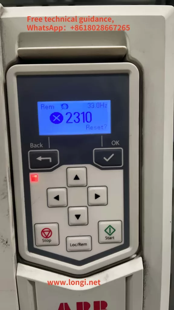
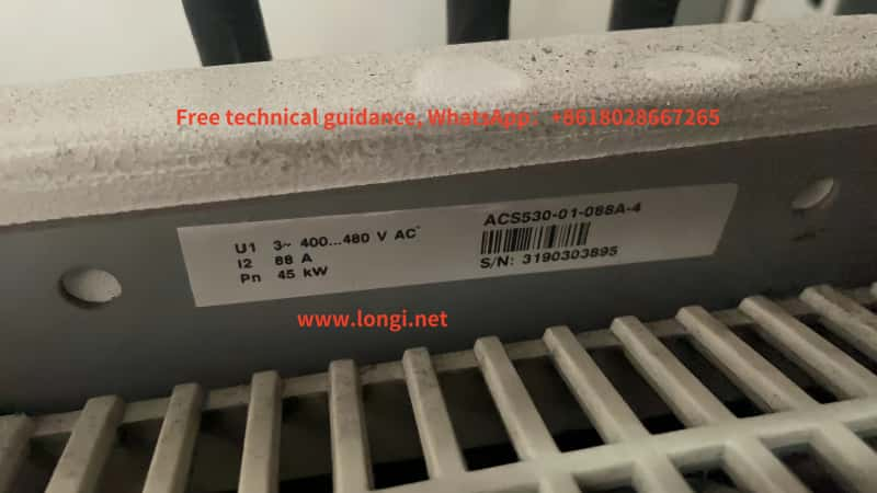
When using ABB’s ACS series inverters, including ACS180, ACS530, ACS580, and ACS880, users may encounter the FAULT 7086 alarm code, which is not explicitly mentioned in the manuals for these models. This article delves into the reasons behind this alarm and provides comprehensive solutions to help users quickly identify and resolve the issue.

Fault 7086 of ABB drive

Background of FAULT 7086 Alarm

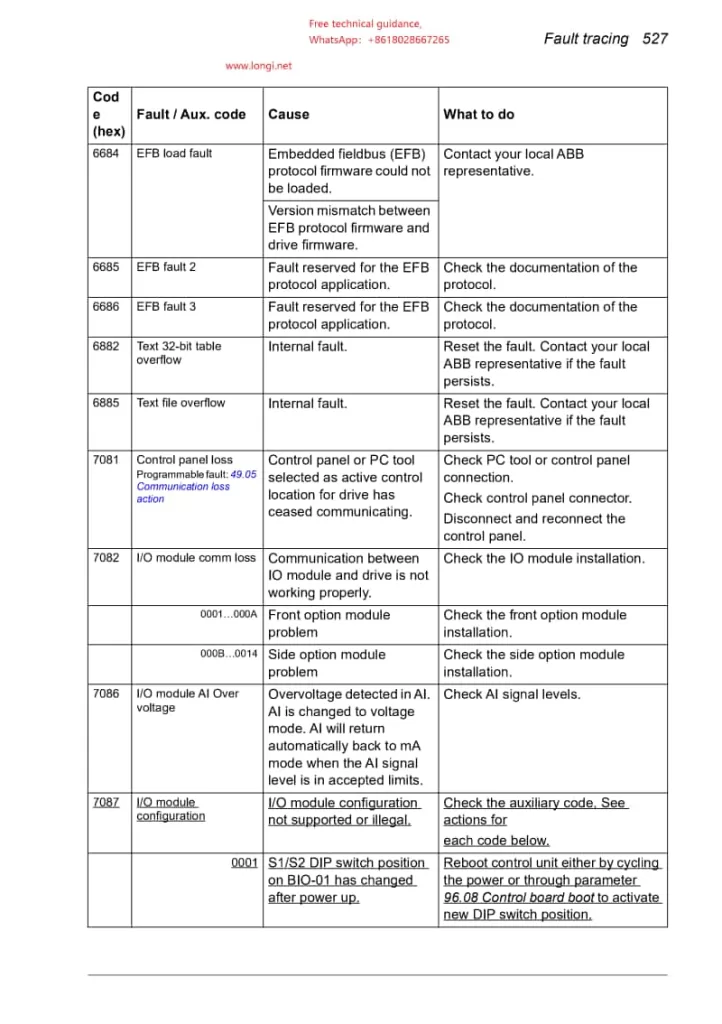
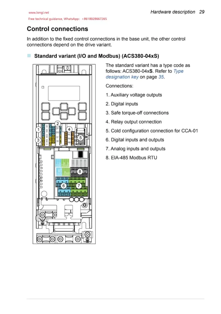
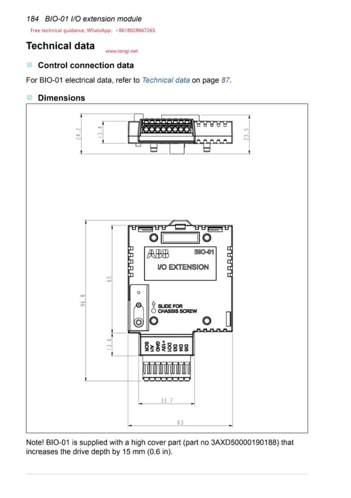
Although the operation manuals for ACS180, ACS530, ACS580, and ACS880 do not directly mention FAULT 7086, the explanation for this alarm code is found in the ACS380 (specifically designed for crane applications) manual. FAULT 7086 indicates “AI Overvoltage in I/O Module,” meaning that an overvoltage has been detected at the analog input (AI) port.

Cause Analysis

AI Port Overvoltage: When the input voltage at the AI port exceeds the set upper limit (typically 10VDC or a configurable value such as 7.5VDC), the inverter triggers the FAULT 7086 alarm to protect internal circuits from damage.

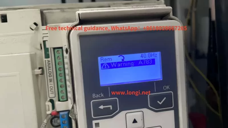
AI Signal Mode Change: If the AI signal level exceeds the acceptable range, the inverter may attempt to automatically switch the AI to voltage mode. If this fails, it will trigger the alarm.

Circuit Board Component Issues: Although the circuit board designs of ACS180, ACS530, ACS580, and ACS880 differ, they share a core control system. Issues with the mainboard, drive board connections, or related components can also lead to unexpected FAULT 7086 alarms.

The posistion of I/O module

Solutions

1.Check AI Voltage:

(1)Use a multimeter to measure the actual input voltage at the AI port and confirm if it exceeds the set upper limit.

(2)Adjust the AI port’s voltage upper limit setting, if necessary, to suit the current operating 2.environment.

(1)Inspect External Connections:

Verify that the external signal source for the AI port is normal, with no abnormal fluctuations or damage.

(2)Check the connection cables and plugs for the AI port to ensure they are securely connected and free from looseness.

3.Examine Circuit Boards and Modules:

(1)If suspecting a circuit board or module failure, first inspect the cables and plugs between the mainboard and drive board, cleaning dust and ensuring good contact.

(2)If possible, try replacing suspected circuit boards or modules to verify if the issue is resolved.

4.Refer to Relevant Documentation:

(1)Although the ACS180, ACS530, ACS580, and ACS880 manuals do not directly mention FAULT 7086, refer to the ACS380 manual for more information on handling AI overvoltage.

(2)Contact our technical team for free technical consultation and assistance

5.Reset the Inverter:

After ruling out external hardware issues, attempt to reset the inverter to see if the alarm clears.

I/O extension module of acs380

Conclusion

The FAULT 7086 alarm in ACS series inverters, including ACS180, ACS530, ACS580, and ACS880, can occur under specific circumstances not directly mentioned in their manuals. By thoroughly analyzing the alarm’s background and causes, and implementing appropriate solutions, users can effectively identify and resolve the issue. During the process, ensure safe operation and back up important data to prevent unexpected losses.

Posted on Leave a comment

ABB Inverter ACS530 Series Alarm 2310: Causes and Solutions

The ACS530 series inverter from ABB, a leading player in industrial automation, is widely utilized across various industries. However, during operation, users may encounter various fault alarms, with alarm code 2310 being a common one, indicating an overcurrent fault. Based on the provided documentation, this article delves into the causes and corresponding solutions for ABB Inverter ACS530 series alarm 2310.

I. Causes of Alarm 2310

1. Excessive Motor Load

When the motor load exceeds its rated capacity, it can lead to a sharp increase in current, triggering the overcurrent protection. This may be due to an overly heavy load driven by the motor, mechanical jams, or motor stalls.

2. Incorrect Inverter Parameter Settings

The parameter settings of the inverter significantly impact its operational performance. Improper settings for acceleration time, deceleration time, or low current limits and overload protections can cause excessive current during motor startup or operation, resulting in an overcurrent alarm.

3. Unstable Power Supply Voltage

Fluctuations in power supply voltage directly affect the output voltage and current of the inverter. Unstable power supply can prevent the inverter from operating steadily, causing the output current to exceed normal ranges and trigger the overcurrent protection.

4. Motor or Cable Faults

Internal motor shorts, open windings, or grounding faults in motor cables can lead to excessive current. Additionally, contactors in the motor cable that are opening or closing can generate instantaneous high currents during switching, causing an overcurrent alarm.

5. Internal Inverter Faults

Damage or aging of internal components such as power modules, drive circuits, or current detection circuits in the inverter can result in unstable output currents, triggering an overcurrent alarm.

II. Solutions

1. Check Motor Load

First, inspect if the motor’s driven load is excessive. If so, attempt to reduce the load or replace the motor and inverter combination with higher capacities. Additionally, check for mechanical jams or stalls and address them promptly.

2. Review and Adjust Inverter Parameters

Examine the inverter’s parameter settings, particularly acceleration time, deceleration time, current limits, and overload protections. Ensure these settings are appropriate for the motor’s actual operational requirements. Adjust them if found to be incorrect.

3. Stabilize Power Supply Voltage

Use a multimeter or similar tools to check the stability of the power supply voltage. If significant fluctuations are present, implement measures to stabilize it, such as installing voltage stabilizers or UPS systems.

4. Inspect Motor and Cables

Examine the motor and motor cables for faults. Check for short circuits or open windings in the motor, verify the insulation resistance of the cables, and ensure no power factor correction capacitors or surge absorbers are present in the cables that could contribute to abnormal currents.

5. Check Internal Inverter Components

If all the above checks are normal, the overcurrent alarm may be due to internal inverter component damage. Contact professional technicians for inspection or replacement of faulty internal components.

III. Preventive Measures

To avoid the occurrence of ABB Inverter ACS530 series alarm 2310, adopt the following preventive measures:

Regular Inspections and Maintenance: Conduct periodic inspections and maintenance of the motor and inverter to ensure their smooth operation.

Appropriate Parameter Settings: When setting inverter parameters, base them on the motor’s actual conditions to prevent incorrect settings from causing overcurrent faults.

Stable Power Supply Voltage: Maintain stable power supply voltage to prevent its fluctuations from affecting the inverter’s performance.

Suitable Motor and Inverter Selection: Choose motors and inverters that match the actual load requirements to prevent overcurrent faults due to excessive loads.

In conclusion, ABB Inverter ACS530 series alarm 2310 is a critical fault alarm that requires attention. By thoroughly examining motor loads, adjusting inverter parameters, stabilizing power supply voltage, inspecting motors and cables, and checking internal inverter components, this issue can be effectively resolved, ensuring the inverter’s smooth operation. Furthermore, implementing preventive measures can reduce the likelihood of overcurrent faults and enhance the reliability and stability of the equipment.