I. Introduction
The Lingshida LSD-B7000 series inverter is a high-performance, multi-functional full-vector variable frequency drive widely used in various industrial control fields. To help users better understand and utilize this inverter, this article will provide a detailed explanation of its panel functions, parameter settings, external wiring, fault code handling, and more.

II. Panel Function Introduction
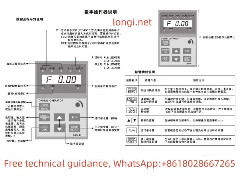
The Lingshida LSD-B7000 series inverter features a clean and intuitive panel design with reasonably laid out function keys for easy operation. The main function keys include:
- RUN Button: Starts the inverter.
- STOP Button: Stops the inverter.
- PROG Button: Enters or exits programming mode for modifying and viewing parameters.
- ▲▼ Buttons: Used to increase or decrease parameter values in programming mode.
- DATA Button: Confirms parameter settings and saves them.
Additionally, the panel is equipped with LED indicators to display the inverter’s operational status and fault information.
III. Parameter Settings
- Selecting the Appropriate V/F Curve
The V/F curve represents the relationship between the output voltage and frequency of the inverter. Selecting the right V/F curve is crucial for ensuring stable motor operation. The LSD-B7000 series inverter offers multiple preset V/F curves. Users can choose based on the motor type and load characteristics by adjusting the Pr015 parameter in programming mode.
- Setting Maximum Frequency, Maximum Voltage, Minimum Frequency, Minimum Voltage, Intermediate Voltage, and Intermediate Frequency
- Maximum Frequency: Sets the highest output frequency of the inverter, adjustable through the Pr016 parameter.
- Maximum Voltage: Sets the highest output voltage, adjustable through the Pr017 parameter.
- Minimum Frequency: Prevents motor overheating at low speeds by setting the lowest output frequency, adjustable through the Pr022 parameter.
- Minimum Voltage: Ensures stable motor operation at low speeds by setting the lowest output voltage, adjustable through the Pr023 parameter.
- Setting Intermediate Voltage and Intermediate Frequency
Adjusting the intermediate voltage and frequency can optimize the inverter’s performance. Users can set two intermediate frequency points and their corresponding voltage values by modifying the Pr018 to Pr021 parameters.
- Setting UP/DOWN Frequency Given Function
The UP/DOWN function allows users to manually adjust the output frequency of the inverter using the ▲▼ buttons on the panel. Enable and adjust this function by modifying the Pr060 and Pr061 parameters in programming mode.
- Jogging Speed Adjustment
Jogging is a temporary method for adjusting the output frequency. Set the jogging frequency by modifying the Pr058 parameter and press the JOG button on the panel to achieve jogging speed adjustment.
IV. External Wiring and Parameter Settings
- External Terminal Forward/Reverse Control
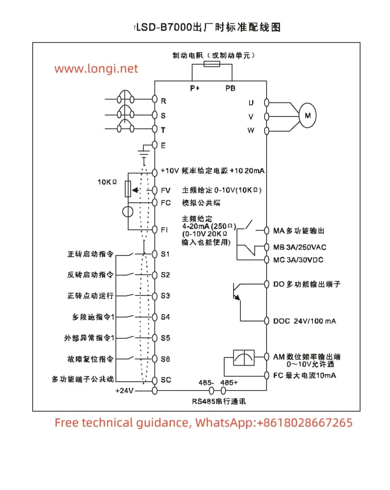
To achieve forward/reverse control via external terminals, connect the forward (FR) and reverse (RR) terminals. In programming mode, select the external terminal control mode by adjusting the Pr005 parameter and set the Pr141 and Pr142 parameters for forward and reverse functions.
- External Potentiometer Speed Control
External potentiometer speed control is a commonly used speed adjustment method. Connect the output end of the potentiometer to the frequency given terminal (e.g., FV terminal) of the inverter. Users can adjust the output frequency of the inverter by rotating the potentiometer. In programming mode, select the external analog voltage given mode by adjusting the Pr004 parameter and set the corresponding FV terminal parameters (e.g., Pr152 and Pr153) to adjust the gain and offset.

V. Fault Code Meaning Analysis and Solutions
The Lingshida LSD-B7000 series inverter features comprehensive fault protection. When a fault occurs, the inverter displays the corresponding fault code. Below are some common fault codes, their meanings, and solutions:
- OC: Overcurrent Protection. May be caused by motor overload or output short circuit. Solutions include checking motor load, output circuit, and parameter settings.
- OV: Overvoltage Protection. May be due to excessive input voltage or damaged brake resistor. Solutions include checking input voltage and brake resistor.
- LU: Undervoltage Protection. May be due to low input voltage. Solutions include checking input power supply and voltage stabilizer.
- EF: External Fault. May be caused by abnormal external input signals. Solutions include checking external input terminals and signal sources.
When encountering a fault code, users should first make a preliminary judgment based on the code’s meaning, then follow the solutions to inspect and repair. If the problem persists, contact Lingshida’s after-sales service center for further technical support.
VI. Conclusion
The Lingshida LSD-B7000 series inverter is a powerful and easy-to-use full-vector variable frequency drive. Through this guide, users can better understand and utilize this inverter, mastering its panel functions, parameter settings, external wiring, and fault code handling. In practical applications, users should set parameters and wire connections based on actual needs, regularly perform maintenance and inspections to ensure the long-term stable operation of the inverter.
