
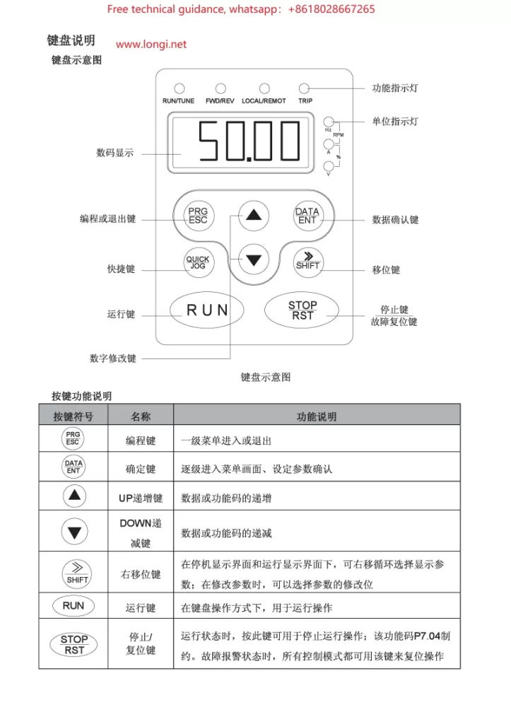
I. Operation Panel (Keyboard) Usage
The operation panel (keyboard) of the CHF100A Series Vector Universal VFD serves as the primary interface for VFD control and parameter setting. Here are the basic keyboard operation methods:
- Power-on and Display:
- Upon connecting the VFD’s power supply, the display on the operation panel will illuminate, showing the current status or default parameters.
- Key Functions:
- PRG: Programming key, used to enter or exit parameter setting mode.
- SHIFT: Shift key, combined with numeric keys to select or modify high-order digits of parameters.
- ESC: Escape key, used to exit the current setting or menu.
- ENT: Enter key, used to confirm current settings or selections.
- DATA: Data toggle key, used in some settings to switch between displaying different data items.
- Parameter Setting Procedure:
- Press the PRG key to enter parameter setting mode.
- Use arrow keys (if equipped) or SHIFT + numeric keys to select the desired parameter number.
- Press the ENT key to enter the parameter’s setting interface.
- Modify the parameter value using arrow keys or numeric keys.
- Press the ENT key again to confirm the setting.
- Press the ESC key to exit parameter setting mode.
II. VFD Terminal Startup and Potentiometer Speed Regulation Wiring
- Terminal Startup Wiring:
- Refer to the electrical wiring diagram in the manual (typically around page 75) to locate the input terminals related to startup (e.g., S1, S2).
- Connect the external startup signal (e.g., pushbutton switch, PLC output) to the corresponding startup terminals.
- Configure parameters as needed to ensure the VFD recognizes and responds to these startup signals.
- Potentiometer Speed Regulation Wiring:
- Locate the analog input terminals (e.g., AI1, AI2) on the VFD, which receive analog signals from the potentiometer.
- Connect the wiper of the potentiometer to the AI1 or AI2 terminal, and the fixed terminal to the common ground (e.g., COM).
- Adjust the potentiometer to vary the output signal, thereby controlling the VFD’s output frequency and motor speed.

III. VFD Fault Code Analysis and Troubleshooting
When a CHF100A Series VFD encounters a fault, it displays the corresponding fault code on its screen. Here are some common fault codes, their analysis, and troubleshooting methods:
- OC (Overcurrent):
- Cause: Excessive motor or load, output short circuit, faulty cabling or wiring.
- Solution: Check the motor and load to ensure they are within normal ranges; inspect cabling and wiring for correctness; increase deceleration time or reduce acceleration current.
- OV (Overvoltage):
- Cause: Excessive input voltage, inadequate deceleration time.
- Solution: Verify that the input voltage meets specifications; increase deceleration time.
- UV (Undervoltage):
- Cause: Insufficient input voltage, power supply failure.
- Solution: Check the power supply voltage for normalcy; inspect power lines and fuses for integrity.
- OH (Overheating):
- Cause: Elevated ambient temperature, poor ventilation, clogged heat sink.
- Solution: Improve ventilation to enhance cooling, reduce ambient temperature; clean dust and debris from the heat sink.
Please note that these are exemplary analyses and solutions. Always refer to actual circumstances and detailed instructions in the manual. When dealing with any electrical fault, adhere strictly to safety procedures and consider power disconnection to avoid electrical shock risks.