Posted on Leave a comment

User Guide for Delta VFD MS300 Series: Operation Panel Usage, Startup and Debugging of VFD Terminal Mode, Analysis and Solutions for VFD Fault Codes

Delta VFD MS300 Series User Guide

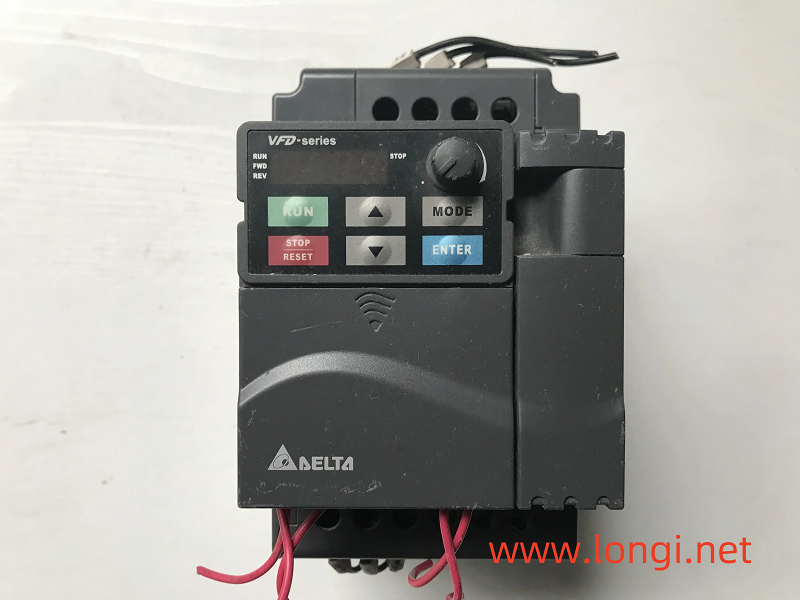
I. Operating Panel Usage

  1. Power-On and Display
    • Upon powering on, the VFD automatically conducts a self-test and then enters standby mode. The display on the operating panel shows the current status and parameters.
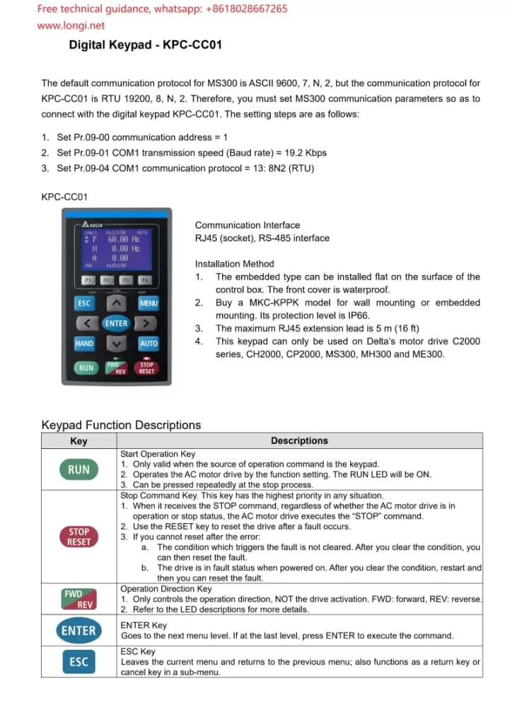
  2. Function Key Operations
    • RUN/STOP Button: Press RUN to start the VFD and STOP to halt its operation.
    • Direction Selection (FWD/REV): Used to select forward or reverse rotation for the motor.
    • Frequency Adjustment Keys: Adjust the output frequency using the up and down arrow keys. In automatic mode, these keys may be disabled.
    • MENU Button: Enters the main menu, allowing access and modification of various settings.
    • ENTER Button: Confirms the current selection or enters setup mode.
    • ESC Button: Exits the current setup or returns to the previous menu level.
  3. Parameter Settings
    • Navigate to the parameter settings menu, use the arrow keys to select the parameter to modify, press ENTER to enter edit mode, adjust the parameter value with the up/down arrow keys, and confirm with ENTER.
digital keypad KPC-CC01 Functional Description

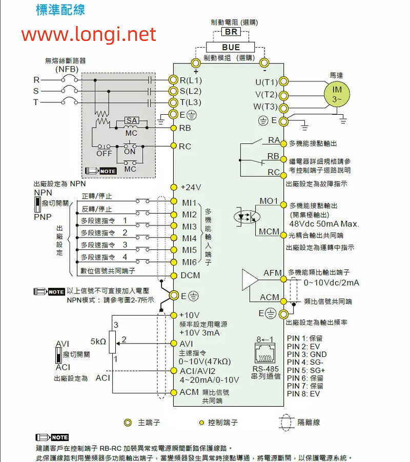
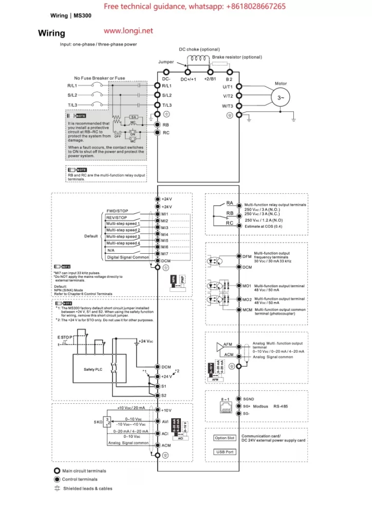
II. Wiring for Terminal Start and Potentiometer Speed Control

  1. Starting Terminal Wiring
    • Forward Start (FWD): Connect the external control signal to the VFD’s forward start terminal (e.g., FWD).
    • Reverse Start (REV): For reverse rotation, connect the signal to the reverse start terminal (e.g., REV). Typically, forward and reverse cannot be activated simultaneously.
    • Stop: Connect the stop signal to the VFD’s stop terminal to interrupt output.
  2. Potentiometer Speed Control Wiring
    • Connect a potentiometer to the analog input terminal (e.g., AVI or ACI) of the VFD. Attach the two fixed ends of the potentiometer to the VFD’s power supply (e.g., +10V and GND), and connect the sliding end to the VFD’s analog input terminal.
    • According to the parameter settings in the manual (e.g., parameter 03-00), configure the relevant parameter to “frequency command” so that the VFD can adjust its output frequency based on the voltage signal from the potentiometer.
MS300 vfd standard wiring diagram

III. Parameter Configuration

  1. Basic Parameter Settings
    • Maximum Operating Frequency (Parameter 01-00): Set the maximum output frequency based on the motor specifications.
    • Acceleration/Deceleration Time (Parameters 01-12 through 01-19): Configure appropriate acceleration and deceleration times to avoid mechanical shocks and overcurrents, tailored to your application’s needs.
    • Starting Frequency (Parameter 01-09): Set the initial frequency at startup to mitigate starting surges.
  2. Input/Output Terminal Configuration
    • Multi-function Input Terminals (Parameters 02-01 through 02-07): Assign each terminal’s function according to your control requirements, such as start, stop, and direction control.
    • Analog Input Configuration (e.g., Parameter 03-00): Specify the function of AVI, ACI, and other analog input terminals, such as frequency reference or torque control.
  3. Protection Parameters
    • Overcurrent Protection (Parameters 06-03 through 06-04): Configure the overcurrent protection threshold and duration to safeguard the motor and VFD.
    • Overvoltage/Undervoltage Protection (Parameters 06-00, 06-01): Set voltage protection thresholds to ensure stable operation amidst voltage fluctuations.

IV. Fault Code Analysis and Resolution

  1. Overcurrent (OC)
    • Cause: Excessive motor load, too short acceleration time, motor malfunction, etc.
    • Resolution: Inspect the motor and load conditions, adjust the acceleration time, and check for motor damage.
  2. Overvoltage (OV)
    • Cause: Excessive input voltage, too short deceleration time, insufficient braking resistance, etc.
    • Resolution: Verify the input voltage, adjust the deceleration time, and consider adding braking resistance.
  3. Undervoltage (LV)
    • Cause: Low input voltage, voltage drop due to long power lines, etc.
    • Resolution: Check the power supply voltage and optimize power line layout.
  4. Overheating (OH)
    • Cause: High ambient temperature, poor heat dissipation, excessive load, etc.
    • Resolution: Improve cooling conditions, reduce the load, and inspect and clean the cooling fan.
  5. Communication Fault
    • Cause: Communication line issues, incorrect parameter settings, address conflicts, etc.
    • Resolution: Examine the communication lines, verify communication parameter settings, and ensure unique device addresses.

By following this guide, you can effectively use and maintain the Delta VFD MS300 series, ensuring stable operation and optimal performance.

Posted on Leave a comment

Global Variable Frequency Drive (VFD) repair center

“Longi Electromechanical” has more than 20 years of experience in industrial control maintenance, and is one of the earliest companies engaged in VFD repair. Equipped with artificial intelligence AI maintenance instruments, it specializes in emergency repair of various equipment, with high technical efficiency. It has repaired more than 200,000 units of equipment, including ultrasonic, robot, charging pile, inverter,Variable Frequency Drive (VFD), touch screen, servo, intelligent instrument, industrial control machine, PLC and other products. General problems can be repaired on the same day. LONGI promises you that “if it can’t be repaired, we won’t charge you”. And it provides lifelong maintenance service and free technical consultation for inspection! For urgent repair consultation, please call the contact number or add WHATSAPP maintenance hotline: +8618028667265 Mr. Guo

From European and American brands to Japanese, Korean, and Taiwanese ones, until various domestic brands, we have repaired countless models and specifications of VFDs. In the process of serving our customers, we have continuously learned and accumulated maintenance experience to enhance our skills. We specialize not only in repairing VFDs but also in summarizing various maintenance experiences, elevating them to a theoretical level. We have published the book “VFD Maintenance Technology” and offered VFD maintenance training, thereby promoting the development of the VFD maintenance industry. Longi Electromechanical Company has repaired VFDs from the following brands:

European and American Brands

ABB drives, SEW drives, LUST VFD, LENZE VSD, Schneider drives, CT drives, KEB VSD, Siemens drives, Eurotherm VFD, G.E. VFD, VACON VSD, Danfoss VFD, SIEI VFD, AB VFD, Emerson VFD, ROBICON VFD, Ansaldo VFD, Bosch Rexroth VSD, etc.

Japanese Brands:

Fuji INVERTER, Mitsubishi INVERTER, Yaskawa INVERTER, Omron INVERTER, Panasonic INVERTER, Toshiba INVERTER, Sumner INVERTER, Tooka INVERTER, Higashikawa INVERTER, Sanken INVERTER, Kasia INVERTER, Toyo INVERTER, Hitachi INVERTER, Meidensha INVERTER, etc.

Taiwanese Brands:

Oulin INVERTER, Delta INVERTER, Taian INVERTER, Teco INVERTER, Powtran INVERTER, Dongling INVERTER, Lijia INVERTER, Ningmao INVERTER, Sanji INVERTER, Hongquan INVERTER, Dongli INVERTER, Kaichi INVERTER, Shenghua INVERTER, Adlee INVERTER, Shihlin INVERTER, Teco INVERTER, Sanchuan INVERTER, Dongweiting INVERTER, Fuhua INVERTER, Taian INVERTER (note: Taian is repeated, possibly a mistake in the original list), Longxing INVERTER, Jiudesongyi INVERTER, Tend INVERTER, Chuangjie INVERTER, etc.

Chinese Mainland brands:

Senlan Inverter, Jialing Inverter, Yineng Inverter, Hailipu Inverter, Haili Inverter, Lebang Inverter, Xinnuo Inverter, Kemron Inverter, Alpha Inverter, Rifeng Inverter, Shidai Inverter, Bost Inverter, Gaobang Inverter, Kaituo Inverter, Sinus Inverter, Sepaxin Inverter, Huifeng Inverter, Saipu Inverter, Weier Inverter, Huawei Inverter, Ansheng Inverter, Anbangxin Inverter, Jiaxin Inverter, Ripu Inverter, Chint Inverter, Delixi Inverter, Sifang Inverter, Geli Te Inverter, Kangwo Inverter, Jina Inverter, Richuan Inverter, Weikeda Inverter, Oura Inverter, Sanjing Inverter, Jintian Inverter, Xilin Inverter, Delixi Inverter, Yingweiteng Inverter, Chunri Inverter, Xinjie, Kemron-Bong Inverter, Nihonye Inverter, Edison Inverter

Other brands:
Migao VFD, Rongqi VFD, Kaiqi VFD, Shiyunjie VFD, Huichuan VFD, Yuzhang VFD, Tianchong VFD, Rongshang Tongda VFD, LG VFD, Hyundai VFD, Daewoo VFD, Samsung VFD, etc.

Longi Electromechanical Company specializes in the maintenance of VFDs and strictly requires its engineers to followlow standard operating procedures. Upon receiving a unit, the engineers carefully inspect its exterior and clarify any fault conditions with the customer before beginning work. Any removed circuit boards are cleaned using ultrasonic cleaning equipment. Repaired circuit boards are coated with high-temperature and high-pressure-resistant insulating paint, dried in a drying machine, and then reinstalled in the VFD, with measures taken to prevent corrosion and interference.

The repaired VFD will undergo a simulated operation with load using a heavy-load test bench to avoid any potential issues that may arise under actual load conditions on site.

When it comes to VFD maintenance, most cases are related to the equipment on site. Sometimes a standalone unit may have been repaired, but it doesn’t work properly when installed on site. In some cases, the problem lies with the system rather than the VFD itself. For such issues, if the customer requests on-site service, we will do our utmost to resolve the problem for them. If the location is far away, such as in another province, we can use tools like video conferencing and phone calls to allow our engineers to remotely diagnose and resolve the on-site issues for the customer.

Posted on Leave a comment

Repair process of driving circuit for 22kW Delta frequency Inverter

After checking the drive circuit of the 22kW Delta VFD Drive and replacing it with a new module, the OC will jump upon startup. The module is newly replaced, and all six drive pulses are working properly. I don’t think it should be. Still checking the measurement, the six negative pressures driving the IC during shutdown are all normal, and the six excitation voltages are also normal after startup. It is necessary to first determine whether the fault is caused by the driver IC or the module.

It is necessary to first test the load carrying capacity of the six drive ICs, that is, to measure the trigger current value of their output. Connect a 15 ohm resistor in series to the output terminal, and then connect a 15 ohm resistor in series to the probe to limit the circuit current to around 0.5A. After the start signal is activated, its current output capacity is measured, and it can still provide a dynamic current of about 150mA even when the original trigger circuit is connected normally. The driving circuit of the V-phase lower arm IGBT tube only outputs about 40mA of current, which obviously cannot meet the excitation requirements of the IGBT tube. The root cause of the OC fault lies in this!
There seems to be a misconception about the driving method of IGBT tubes, especially high-power IGBT tubes: IGBT tubes are voltage signal excitation devices, not current type excitation devices. The driving signal only needs to meet the voltage amplitude, without requiring too much current driving capability! I have previously analyzed that even IGBT tubes are essentially current driven devices!
The output signals of the driving ICs (PC929 and PC923) of the machine are amplified by a complementary voltage follower and then supplied to the triggering terminals of the module. The push-pull amplifier was originally a pair of field-effect transistors, but due to the lack of the original type of transistor on hand, it has now been replaced with transistor pairs D1899 and B1261. After modification testing, it should be able to meet the excitation requirements. Check the V-phase lower arm circuit. The resistance from pin 11 (pulse output pin) of PC929 to the subsequent power amplifier circuit was originally 100 ohms, but now it has changed to over 100k, causing D1899 to be unable to fully conduct and the output driving current to be too small. After replacing the resistor, the output current is normal. After replacing the power transistor, the base resistance was not measured, resulting in this phenomenon.
By the way, I measured the negative current supply capacity of the driving circuit when cutting off negative pressure output. The probe is still connected in series with a 15 ohm resistor, and each circuit is around 30mA.
This leads to the conclusion that measuring the output voltage of the driving IC is not as direct and effective as measuring its output current. And it can expose the root cause of the malfunction. When the internal resistance of the circuit output increases due to certain reasons, measuring the driving voltage is often normal, which masks the truth of insufficient driving current.

Posted on Leave a comment

How to handle the password lock of VFD-E Delta VFD converter?

I helped a friend debug a Delta VFD-E frequency converter on site, but due to a damaged panel, I couldn’t operate it after purchasing a panel provided by a friend. This friend went to the site and adjusted it all morning, but the frequency converter still couldn’t run. When I arrived at the site, I found that the parameters couldn’t be changed. The machine parameters 00.08 and 00.09 are for protecting password input and protection password setting, respectively. When the 00.09 parameter is assigned a value of 1, it indicates that the parameter has been locked by divisor. The correct password needs to be entered from parameter 0.08. After the value in parameter 00.09 becomes 0, all parameters can be operated. However, before changing the panel, the machine is said to be functional. In theory, You can use it by replacing the good panel. It’s impossible to set the password on your own after replacing the panel. Someone must have accidentally changed the 00.08 parameter! I don’t know the password! The factory personnel called to inquire about multiple people, but I’m not sure if there’s anything else they can do. Should we withdraw now? The machine is not running yet. It cannot be produced. We need to try to make the machine run. Although the parameters cannot be modified, they can be called up for monitoring. Therefore, we can call up parameters 02-00 and 02-21, which are frequency commands and operation commands. Both parameters have a value of 1, which is controlled by terminal start/stop and external potentiometer. The start/stop of the machine was originally wired through terminals, and a torsion switch has been connected to terminals M11 and DCM for starting, Stop the control. Find a 1k potentiometer, connect terminals+10VAV1 and ACM, power on and test the machine. The machine is running! The manufacturer’s personnel are very happy and eager to ship. The operators also feel that using a potentiometer for speed regulation is even more convenient than panel speed regulation.

After multiple efforts, we finally obtained the super password for this frequency converter. Parameter 008 is a password item, and entering the 8333 super password can unlock it. If you encounter similar problems in the future, you can unlock it through the super password and then operate it without changing the control method to complete the task.

Posted on Leave a comment

Three Examples of IGBT Module and Driver Fault Frequency Converter Maintenance Process

A. One Dongyuan 7300PA3.7kW frequency converter was sent for repair. The power was connected and it was detected that there was output in the U, V, and W phases, but there was severe phase deviation. It was determined that the drive circuit was abnormal or the module was damaged. Measure the open circuit of the upper arm diode inside the U-phase power stage of the inverter circuit. In general, the IGBT transistor connected in parallel with this diode is also often damaged. In fact, the IGBT tubes were first burnt out by short-circuit current, and the parallel diodes were also damaged by the impact.

After removing the inverter module SPIi12E, all the pins of the inverter module are empty, and the six drive circuits are ready to be tested when powered on. Once powered on, the frequency converter experiences an overheating fault, and the CPU locks the output of the drive pulse in the fault state. Due to the absence of trigger pulse output, it is impossible to detect the quality of the driving circuit. The locking state of the overheating fault must be temporarily released before checking the quality of the drive circuit.
Observe that the inverter module on the circuit board has two terminals labeled T1 and T2, which may be the internal overheat alarm output terminals of the module. One end is led into a 5V power supply through a resistor, and the other end is grounded. When this terminal is suspended, T1 terminal outputs a high-level module overheating signal through an pull-up resistor to protect the shutdown. After short circuiting the T1 and T2 terminals, there will be no protective shutdown when power is supplied.
Check that there is no trigger pulse output in the IGBT drive circuit of the U-phase upper arm. After replacing the drive circuit IC/PC923, the six pulse outputs are normal.
After replacing the IGTB inverter module with a new one, remove the short circuit of the T1 and T2 terminals, and conduct a power test to ensure normal operation. Experience has shown that when an IGBT tube is damaged, the corresponding drive IC will also be damaged due to impact. It is also necessary to inspect the drive IC of the same branch of the damaged module and not hastily replace it with a new module to avoid causing damage to the new module again due to abnormal drive circuit!
B. An Alpha 18.5kW frequency converter with six single tube IGBT tubes (modules) forming a three-phase output circuit, one of which is damaged. CPU motherboard jumps 2501, panel operation fails. The cause of the malfunction of the machine was damage caused by lightning strikes.

The operation panel shows 2501 when powered on, and all operations are malfunctioning. CPU motherboard malfunction, caused by damage to the CPU and peripheral communication circuits. Let’s not worry about it for now. First, fix the driver board before proceeding.
Check the driving circuit, a total of six A316J chips are responsible for six driving pulse output tasks. Three drive circuits that output upper arm pulses are damaged, but there are no integrated circuits of the same model available for replacement. Based on the experience of repairing other brands of frequency converters, using only three A316J chips (used for three-phase lower arm drive) as the three-phase OC signal alarm output can meet the protection requirements. Therefore, the other three pieces were replaced with 3120 (same as PL250V) to drive the optocoupler IC. The original IC was packaged in a 16 pin dual row SMT package, and the replaced IC was packaged in an 8-pin dual row inline package. But the connection is also relatively convenient. Only weld the 8 pins of the new IC to the original 12/13 pins, weld the 5 pins of the new IC to the original 9/10 pins, and connect the 6/7 pins of the new IC to the original 11 pins; Due to the original IC input method being an operational amplifier input and the new IC being a photoelectric tube input, a larger input current is required. Remove the 202 grounding resistor from the original input side and replace it with a 5.1k resistor. Connect the 3 pins of the new IC to ground, and connect the original 1 pin in series with a 300 ohm resistor to the 2 pins of the new IC. Power on and test, and the static voltage is normal.
At this point, after replacing the CPU motherboard with a new one, the static output negative pressure and dynamic pulse output of the six drive circuits were tested to be normal upon power on. After replacing the damaged IGBT module, the machine was tested normally.

C. A 7.5kW frequency converter has been reported by the user as having no major issues, but it has output but cannot operate due to phase deviation. Check if there is an abnormality in one of the six driving circuits. The driving IC model is PC929 (or A4503?). Measure that there are no pulse outputs on the input and output sides of the driving IC. The input side of the IC is directly connected to the pulse output terminal of the CPU. Suspecting a faulty internal pin circuit of the CPU, the PC929 input terminal was disconnected. The voltage at the CPU pulse output terminal increased, but as soon as the driver IC was connected, it dropped to nearly 0V.
Analysis: Due to the direct output of the CPU driving the photoelectric tube, it needs to output a large current. Long term operation may cause aging and failure of the output stage or other faults, resulting in an increase in output internal resistance. When unloaded, there is a certain amplitude of voltage signal, but once connected to the load, even if the signal voltage drops significantly. Replacing the CPU motherboard for this malfunction is a quick solution. One reason is that the maintenance cost is high, and the other reason is that it still needs to be purchased externally, and the repair time required by the user is very tight. Isn’t there a better way? Based on the above analysis, although the pulse output pin of the CPU has aging and failure phenomena, which greatly reduces its load capacity, assuming that its signal current is not used and only its output voltage signal is used, this defect can still be remedied to achieve the purpose of repair. By passing the CPU pin through an external amplifier stage, the signal voltage should meet the requirements for driving the photodiode (PC929 input side photodiode).
Measure that both pins on the input side are 5V high level, and the pin connected to the CPU is a negative pulse input. If you have a PNP transistor on hand, connecting one transistor and a 5k resistor should be able to complete the task. But I only have NPN type transistors on hand, which can only be achieved by using two inverters. Disconnect one pin of the driver IC from the CPU output, connect the copper foil strip to a 50k resistor, and then connect the base of the transistor. Connect the collector in series to the base of the next transistor, and then connect it to+15V through a 10k resistor. Ground the two emitters and connect the lower collector to the disconnect pin of the driver IC. Power on test machine, six pulse outputs are normal. Restore the power supply to the inverter module, and the three-phase voltage output is normal.
The CPU of this machine is damaged and faulty. After using two resistors and two transistors, the problem was resolved and successfully repaired.