PowerFlex 750 Series AC Drive User Guide
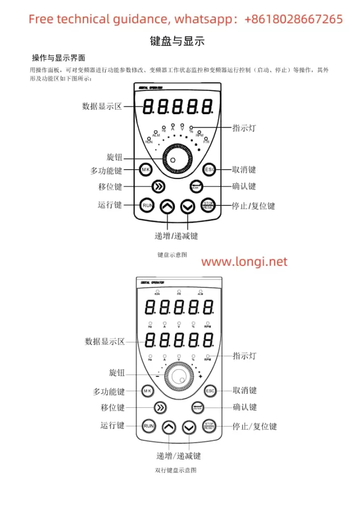
1. Operation Panel (Keypad) Usage
The operation panel (keypad) of the PowerFlex 750 series AC drive serves as the primary interface for user interaction. It allows users to navigate menus, set parameters, and view status information.

Navigation and Selection: Use the arrow keys to navigate through menus and the “Select” button to enter specific settings or parameter editing mode.
Parameter Editing: In edit mode, enter or adjust parameter values using the numeric keys or arrow keys.
Saving and Exiting: After making changes, use the “Save” button to save modifications and the “Exit” button to return to the previous menu or the main interface.
Status Viewing: Select the appropriate option from the menu to view the drive’s output frequency, current, voltage, fault codes, and other status information.
2. Open-Loop V/F Control Parameter Settings
In open-loop V/F (Volts per Hertz) control mode, the drive regulates the motor speed by adjusting the ratio between the output voltage and frequency. Here are guidelines for setting key parameters:
- P35 (Motor Control Mode): Set to “V/Hz” mode to enable open-loop V/F control.
- P25 (Motor Nameplate Voltage): Enter the motor’s rated voltage.
- P27 (Motor Nameplate Frequency): Input the motor’s rated frequency.
- P60 (V/F Curve Settings): Adjust the V/F curve as needed to optimize motor performance.
- P520/P521 (Maximum Forward/Reverse Speed): Set the maximum operating frequency limits for the motor.
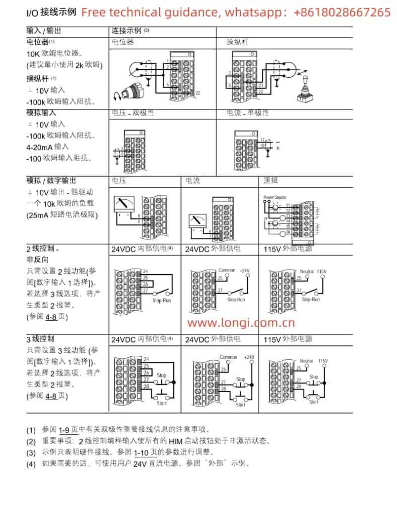
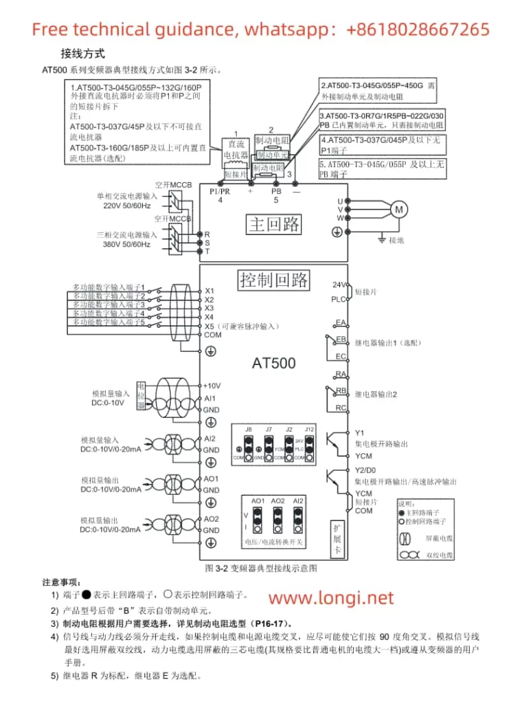
3. Terminal Start and Potentiometer Speed Adjustment Wiring and Parameter Settings
Wiring Instructions:
- Main Power and Control Power Connection: Connect the three-phase main power and (if required) control power as specified in the manual.
- Motor Connection: Wire the motor’s three-phase leads to the U, V, W output terminals.
- Start/Stop Terminal Connection: Connect the contacts of the external start/stop buttons to the drive’s DI (Digital Input) terminals and configure the related parameters.
- Potentiometer Speed Adjustment Connection: Connect the potentiometer’s wiper to the AI (Analog Input) terminal for speed regulation.
Parameter Settings:
- Digital Input Configuration: Configure relevant parameters to assign DI terminals for start/stop functions.
- Analog Input Configuration: Ensure AI terminals are set as the speed reference source and adjust the input range to match the potentiometer’s output range.
- Speed Reference Selection: Specify the analog input as the source for speed references in the parameters.
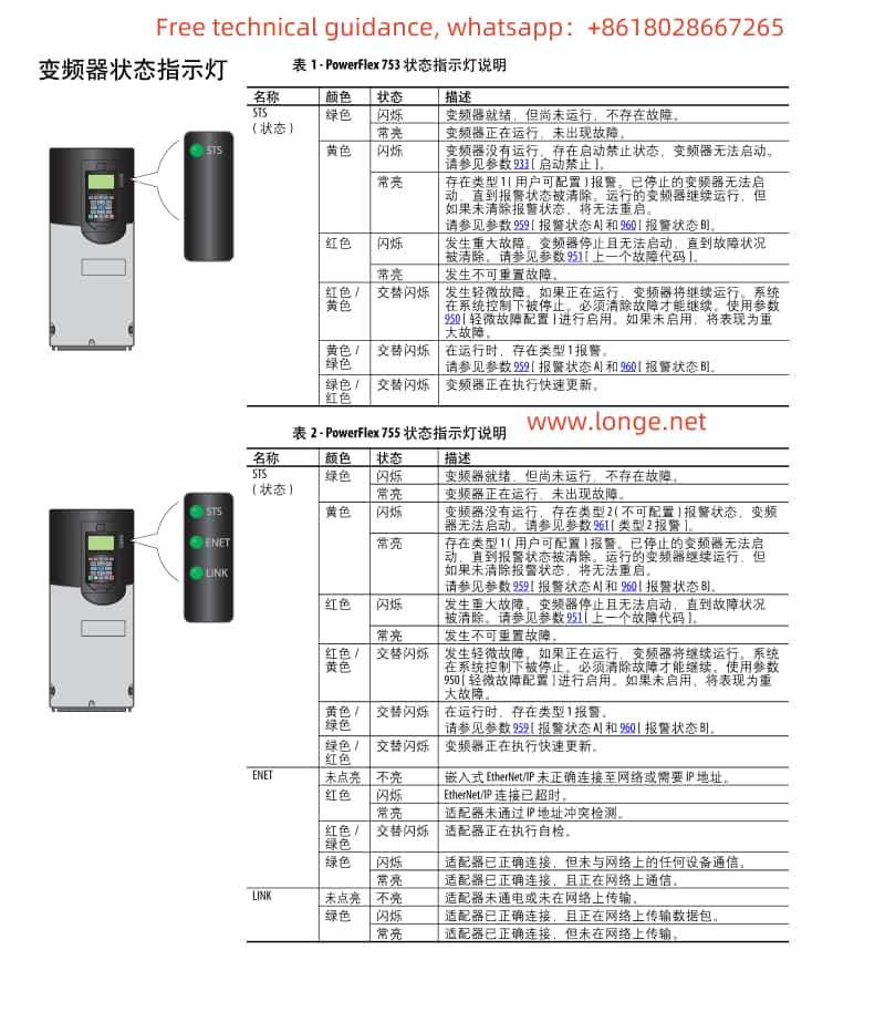
4. Fault Code Analysis and Troubleshooting Summary
According to the fault code list provided in the manual (pages 316-323, fault numbers 0-155), here are summaries of a few common faults, their possible causes, and troubleshooting methods:
- F001: Overcurrent Protection. Check for motor overload, stable power supply voltage, and short circuits in the output circuit.
- F002: Overvoltage Protection. Verify that the input voltage is within the allowed range and consider installing a voltage stabilizer or adjusting the input filter.
- F003: Undervoltage Protection. Check if the power supply voltage is too low and confirm correct power line connections.
- F004: Overheat Protection. Inspect the drive and motor cooling, clean dust from the heat sink, and ensure proper ventilation.
- F005: Communication Failure. Check communication line connections, verify correct communication parameter settings (including baud rate, data bits, etc.).
Please note, the above fault codes are examples, and specific fault codes and their solutions should be referenced directly from the manual.
5. General Troubleshooting Steps
- Check Fault Code: Read and record the fault code on the operation panel.
- Consult the Manual: Look up the corresponding fault description, possible causes, and solutions in the manual.
- Perform Preliminary Checks: Examine power sources, motors, communication lines, etc.
- Reset the Drive: If initial checks reveal no issues, attempt to reset the drive to clear temporary faults.
- Advanced Diagnostics: If problems persist, professional tools may be