Introduction
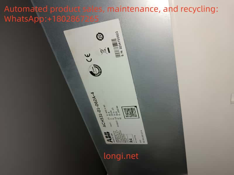
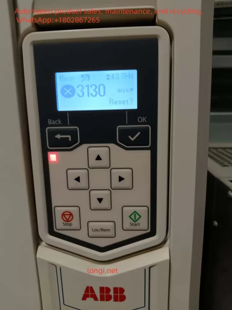
The ABB inverter ACH531 is a high-performance drive equipment widely used in HVAC (Heating, Ventilation, and Air Conditioning) systems. However, during operation, various fault alerts may be encountered, with the 3130 fault being a relatively common one. This article will provide a detailed analysis of the meaning of the 3130 fault in the ABB inverter ACH531 and propose corresponding solutions to help technicians quickly locate and resolve the issue, ensuring stable operation of the equipment.

I. Meaning of the 3130 Fault
The 3130 fault in the ABB inverter ACH531 is defined as an input phase loss fault, also known as a DC voltage oscillation fault. The appearance of this fault code indicates that the inverter has detected an issue with the input power supply, resulting in fluctuations in the DC bus voltage exceeding the normal range (exceeding 13%). This fault typically causes the inverter to shut down to protect the motor and drive system from damage.
II. Cause Analysis of the 3130 Fault
- Power Phase Loss or Fuse Blowing:
- When one phase of the input power supply to the inverter is missing or a fuse blows, it can lead to instability in the DC circuit voltage, triggering the 3130 fault.
- Excessive DC Filter Capacitor Discharge and Insufficient Power Supply:
- The DC filter capacitors inside the inverter are used to smooth the DC bus voltage. If the capacitors discharge excessively and the power supply is insufficient, it can cause increased fluctuations in the DC bus voltage, leading to the 3130 fault.
- Power Grid Interference:
- Interference factors such as imbalances, harmonics, or transient overvoltages in the power grid can affect the normal operation of the inverter and trigger the 3130 fault.
- Oscillation Issues Under Heavy Loads:
- Under heavy load conditions, if the inverter’s parameter settings are unreasonable or the load fluctuates significantly, it may also cause DC bus voltage oscillation, leading to the 3130 fault.
- Hardware Failures:
- Hardware failures such as the rectifier bridge, thyristors, and their trigger circuits inside the inverter may also cause the 3130 fault.

III. Solutions for the 3130 Fault
- Check Power Supply and Fuse:
- First, check whether the input power supply to the inverter is stable and whether the three-phase voltage is balanced. Use a multimeter to measure the incoming voltage and ensure that the voltage of each phase is within the normal range.
- Check whether the fuse has blown and, if so, replace it with a new one promptly.
- Check Rectifier Bridge and Thyristors:
- Examine the thyristors and their trigger circuits inside the rectifier bridge for anomalies. An oscilloscope can be used to observe the trigger waveform of the thyristors to ensure their normal operation.
- If a thyristor or trigger circuit fault is found, it should be replaced or repaired in a timely manner.
- Test DC Bus Voltage:
- Test the actual value of the DC bus voltage under load to see if it fluctuates. If the actual value does not fluctuate while the detected value does, it may indicate a fault in the detection circuit.
- In such cases, consider replacing the relevant detection components, such as sensors or circuit boards.
- Check Capacitor Capacity:
- Check whether the capacity of the DC filter capacitors has decreased. If the capacitor capacity is insufficient, replace it with a new one to improve the stability of the DC bus voltage.
- Check Power Input Terminal:
- Examine whether the wiring at the power input terminal is secure, with no loosening or poor contact.
- Check whether the capacity of the power supply transformer meets the load requirements of the inverter system. If the transformer capacity is insufficient, replace it with a larger one.
- Check whether the switches or circuit breakers are qualified, whether the fuse has blown, and whether the thermal relay has tripped.
- Adjust Parameter Settings:
- Under heavy load conditions, try adjusting the inverter’s parameter settings, such as increasing acceleration and deceleration times or optimizing load balancing designs, to improve the stability of the DC bus voltage.
- If needed, the 3130 fault can be masked by setting parameter 31.21 (input phase loss) to “0”, so that the inverter will not trip when it detects input phase loss. However, please note that this method is only a temporary measure, and the root problem still needs to be solved in the long run.
- Check Other Hardware Faults:
- If the above methods fail to resolve the issue, further examine other hardware components inside the inverter, such as the RTAC (Real-Time Adaptive Control) module and the AIBP (Input Bridge Protection Board), for damage or poor insertion.
- If hardware faults are found, replace or repair the corresponding components promptly.
IV. Conclusion
When the ABB inverter ACH531 encounters the 3130 fault, it should be troubleshooted and resolved from multiple aspects, including the power supply and fuse, rectifier bridge and thyristors, DC bus voltage testing, capacitor capacity, power input terminal, parameter settings, and other hardware faults. Through systematic inspection and adjustment, the 3130 fault can be effectively located and resolved, ensuring stable operation of the inverter. Meanwhile, it is also recommended to regularly maintain and service the inverter to prevent faults from occurring.
