
I. Operation Panel Function Introduction
The operation panel of the Fuji INVERTER FRENIC 5000 G11S/P11S series is the primary interface for user interaction with the frequency converter. It is equipped with a series of buttons and an LED display for setting parameters, monitoring operating status, and executing control operations.
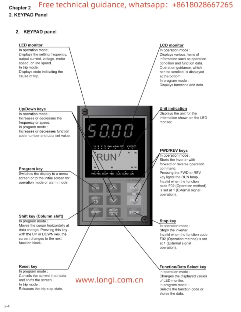
1.1 Button Functions
- FWD/REV Keys: Used to start the frequency converter, enabling the motor to rotate forwards or backwards.
- STOP Key: Used to stop the frequency converter.
- ∨ or ∨ Keys: In program mode, these keys are used to vertically move the cursor to select function codes or data.
- FUNC DATA Key: In program mode, this key is used to store modified data or switch display screens.
- RESET Key: In program mode, this key is used to cancel the current input data; in fault mode, it is used to release the fault stop status.
- PRG Key: Used to switch between operation mode and program mode.
- SHIFT Key (Column Shift): In program mode, when used in combination with the ∨ or ∨ keys, it moves the cursor horizontally.
1.2 Restoring Factory Default Parameter Settings
To restore factory default parameter settings, follow these steps:
- Press the PRG key to enter program mode.
- Use the ∨ or ∨ keys to select “1. DATA SET”.
- Press the FUNC DATA key to confirm the selection.
- Simultaneously press the STOP key and the ∨ key to change the parameter protection value from “1” to “0”, allowing parameter modifications.
- Again, use the ∨ or ∨ keys to select “F00 Data protection” and set its value to “0”.
- Press the FUNC DATA key to save the settings. The frequency converter will restart and restore the factory default parameters.
1.3 Setting and Clearing Passwords
The Fuji FRENIC G11S/P11S series provides password protection to restrict access to parameters. However, the specific methods for setting and clearing passwords are not detailed in the provided manual. Typically, such functions may require setting through specific parameter codes, and the unlocking process may involve the manufacturer or authorized service personnel. It is recommended to refer to Fuji’s official technical support documentation or contact the manufacturer for detailed guidance.
II. Terminal Start/Stop and Potentiometer Speed Regulation
2.1 Terminal Start/Stop
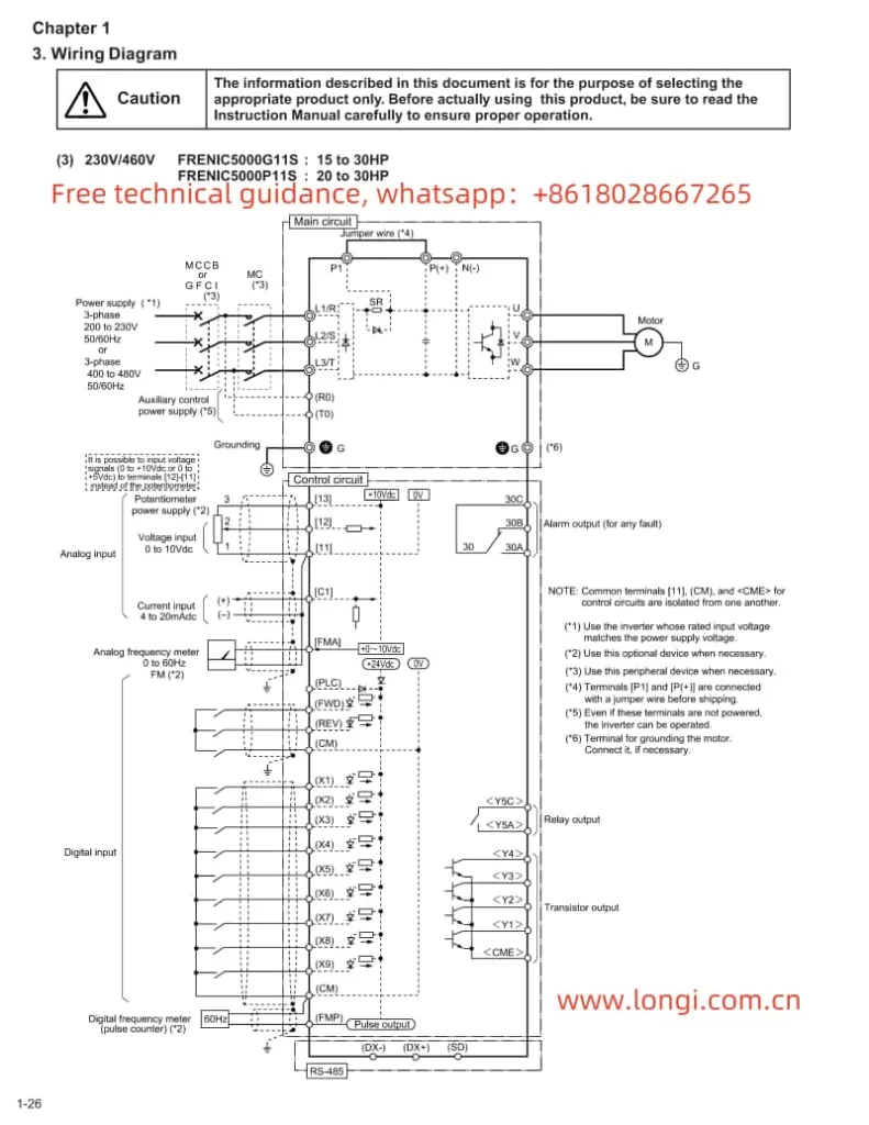
The Fuji FRENIC G11S/P11S series supports start/stop control via external terminals. To achieve this, relevant parameters need to be set correctly, and wiring must be done accordingly:
- Parameter Setting: Set function code F02 to “1” to select external signal input mode.
- Wiring: Connect the control power to terminals R0 and T0; connect the start signal (e.g., FWD) to the corresponding digital input terminal (e.g., X1); connect the stop signal to the REST terminal.
2.2 Potentiometer Speed Regulation
Potentiometer speed regulation is a method of changing the frequency output by adjusting the resistance value of an external potentiometer. The setup steps are as follows:
- Parameter Setting: Set function code F01 to “1” to select voltage input mode.
- Wiring: Connect the output terminal of the potentiometer to the frequency setting terminal of the frequency converter (e.g., terminal 12), and simultaneously ground the common terminal of the potentiometer (e.g., 0V terminal).
III. Frequency Converter Fault Code Analysis and Solutions
When the Fuji FRENIC G11S/P11S series encounters a fault, it will display the corresponding error code, helping users quickly locate the problem. The following are some common fault codes, their analyses, and solutions:
- OC1: Overcurrent during acceleration. Possible causes include motor blockage, excessive load, or improper parameter settings. Solutions include checking the motor and load status, and adjusting acceleration time and current limit parameters.
- OU: DC bus overvoltage. Possible causes include braking resistor failure, excessively short deceleration time, or abnormal supply voltage. Solutions include checking the braking resistor and wiring, and adjusting deceleration time and voltage limit parameters.
- OL: Electronic thermal relay overload. Possible causes include motor overload, poor heat dissipation, or improper parameter settings. Solutions include checking the motor load and heat dissipation conditions, and adjusting the overload protection parameters.
- Er1: Memory error. Possible causes include internal frequency converter faults or program abnormalities. Solutions include restarting the frequency converter; if the problem persists, contact the manufacturer for repair.
Summary
The Fuji Inverter FRENIC 5000 G11S/P11S series user manual provides detailed operation guides and parameter setting instructions, helping users fully utilize the various functions of the frequency converter. Through this guide, users can understand the functions of the operation panel, the method for restoring factory default parameter settings, the setup steps for terminal start/stop and potentiometer speed regulation, as well as the analysis and solutions for common fault codes. This information is crucial for ensuring the normal operation and efficient use of the frequency converter.