
I. Function Introduction of VFD Operation Panel (Keyboard)
The operation panel (keyboard) of the INVT Goodrive 10 series INVERTER serves as the primary interface for user interaction. This keyboard is highly functional, capable of performing basic operations, status monitoring, and parameter settings on the INVERTER. Here are some key functions:
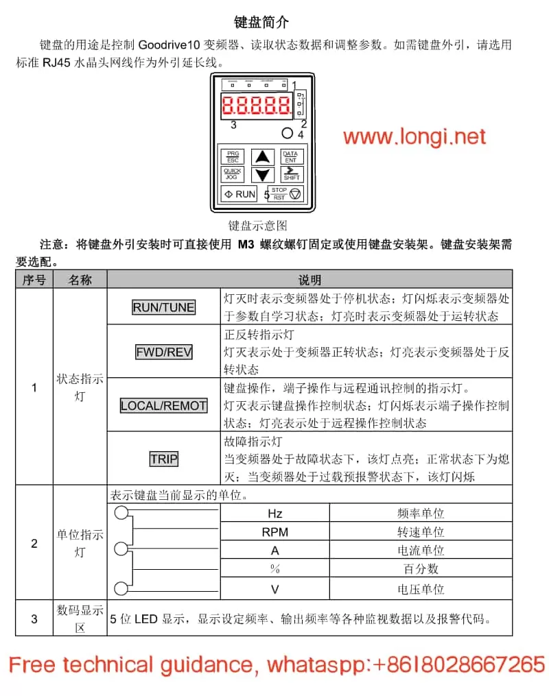
- Status Indicators:
- RUN/TUNE: Indicates whether the INVERTER is running.
- FWD/REV: Indicates the forward or reverse rotation status of the motor.
- LOCAL/REMOT: Indicates the current control mode (local keyboard control or remote communication control).
- TRIP: Indicates whether the INVERTER is in a fault state.
- Digital Display Area: A 5-digit LED display for showing set frequencies, output frequencies, currents, voltages, and various monitoring data and alarm codes.
- Operation Buttons:
- PRG/ESC: Programming key for entering or exiting the parameter setting menu.
- DATA/ENT: Confirmation key for validating parameter settings or entering the next menu level.
- UP/DOWN: Increment/decrement keys for adjusting parameter values.
- SHIFT: Right shift key for selecting different modification bits during parameter setting.
- RUN/STOP/RST: Run/Stop/Reset keys for controlling the start, stop, and fault reset of the INVERTER.
- QUICK/JOG: Quick multifunction key, whose function is set by parameter P07.02 and can include jogging, display state switching, etc.
II. Methods for Setting and Deleting Passwords on the INVERTER
- Setting a Password:
- Enter the parameter setting menu (press PRG/ESC). Locate parameter P07.00 and set it to a non-zero value, which will serve as the user password. After exiting the parameter setting menu, password protection will be activated.
- Deleting a Password:
- Set parameter P07.00 to 0 to disable password protection. Note that password deletion must be performed without password protection in place.
III. Steps to Restore the INVERTER to Factory Defaults
To restore the INVERTER to its factory settings, follow these steps:
- Enter the parameter setting menu (press PRG/ESC).
- Locate parameter P00.18 and set it to 1 (restore default values). The INVERTER will begin restoring default parameters, which may take a few seconds.
- After restoration, parameter P00.18 automatically reverts to 0. At this point, the INVERTER has been restored to its factory settings.
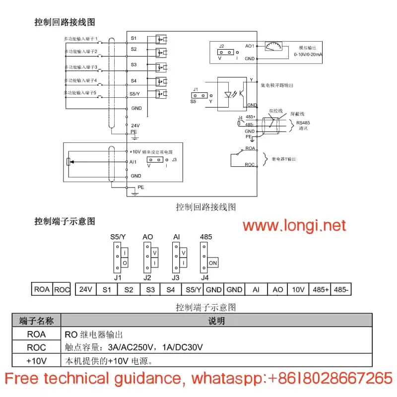
IV. Specific Steps for Terminal Start/Stop and External Potentiometer Speed Adjustment
Wiring Steps:
- Start/Stop Terminal Wiring:
- Connect the start signal from the external control circuit to the S1 terminal of the INVERTER and the stop signal to the S2 terminal.
- Ensure that the control circuit power matches the INVERTER’s control power.
- External Potentiometer Wiring:
- Connect the output end of the potentiometer to the AI1 terminal (analog input terminal) of the INVERTER.
- Connect the power end of the potentiometer to an appropriate power source, typically a 10V DC power supply.
Parameter Setting Steps:
- Set the Run Command Channel:
- Enter the parameter setting menu and locate parameter P00.01. Set it to 1 (terminal run command channel).
- Set the Analog Input Function:
- Locate parameter P00.06 and set it to 1 (keyboard analog AI1 setting). This way, the frequency of the INVERTER will be determined by the analog input from the AI1 terminal.
- Adjust Other Related Parameters (if necessary):
- Adjust acceleration time, deceleration time, maximum output frequency, and other parameters based on actual application requirements to achieve optimal control performance.
V. Analysis and Solution of INVERTER Fault Codes
The Goodrive 10 series INVERTER features comprehensive fault protection functions, capable of monitoring the INVERTER’s operating status in real-time and providing fault codes when issues arise. Here are some common fault codes and their solutions:
- OV1 (Acceleration Overvoltage):
- Possible Causes: Excessively high input voltage; too short deceleration time.
- Solutions: Check if the input voltage is normal; increase the deceleration time as needed.
- OC1 (Acceleration Overcurrent):
- Possible Causes: Excessive load; low grid voltage.
- Solutions: Check if the load exceeds the INVERTER’s rated load; check if the grid voltage is normal.
- UV (Bus Undervoltage Fault):
- Possible Causes: Low grid voltage; input power phase loss.
- Solutions: Check if the grid voltage is normal; check for input power phase loss.
- OH2 (Inverter Module Overheat Fault):
- Possible Causes: High ambient temperature; poor heat dissipation.
- Solutions: Improve the INVERTER’s heat dissipation conditions; reduce the ambient temperature.
When the INVERTER encounters a fault, users should first refer to the fault code to identify possible causes and apply the corresponding solutions. If the problem persists, contact INVT’s technical support for assistance.
VI. Conclusion
The user manual for the INVT Goodrive 10 series INVERTER serves as an essential reference for users to operate and maintain the INVERTER. This document provides detailed information on the INVERTER’s operation panel functions, password setting and deletion, steps to restore factory defaults, specific procedures for terminal start/stop and external potentiometer speed adjustment, as well as fault code analysis and solutions. We hope this content will help users better utilize and maintain the Goodrive 10 series INVERTER.