I. Introduction
The LCGK (ZTV) LC400E series high-performance vector inverter boasts remarkable performance and flexible control functions, making it widely applicable in textile, paper, wire drawing, machine tools, packaging, food processing, fans, pumps, and other automated production equipment. This article aims to provide users with a detailed operation guide for the LC400E series inverter, covering panel function introductions, parameter initialization, password setting and removal, terminal start/stop operations, external potentiometer speed adjustment, and fault code analysis and troubleshooting methods.

II. Inverter Panel Function Introduction
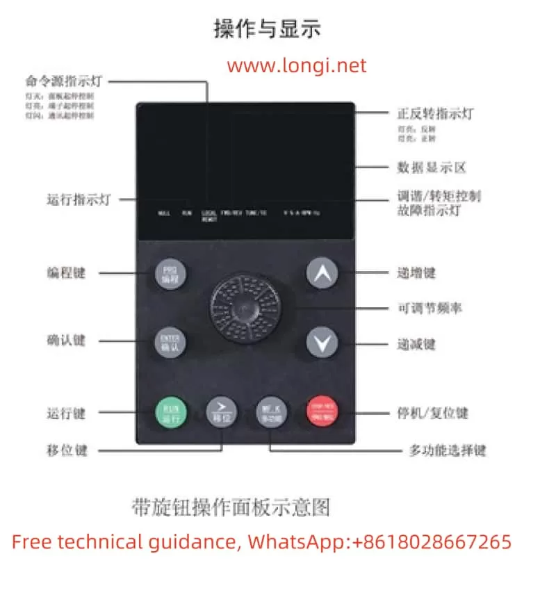
The LC400E series inverter is equipped with an intuitive and user-friendly operation panel. The primary function keys include the Programming Key (PRG), Enter Key (ENTER), Increment Key (Δ), Decrement Key (∨), Run Key (RUN), Stop/Reset Key (STOP/RES), and Multi-Function Key (MF.K). These keys allow users to easily modify parameters, monitor operating status, and control the inverter.
- Programming Key (PRG): Used to enter or exit the function parameter settings interface.
- Enter Key (ENTER): Used to confirm parameter settings or enter the next menu level.
- Increment Key (Δ) and Decrement Key (∨): Used to modify parameter values or select function codes.
- Run Key (RUN): Used to start the inverter.
- Stop/Reset Key (STOP/RES): Used to stop the inverter or reset fault alarms.
- Multi-Function Key (MF.K): Achieves different function switches based on the P7-00 parameter setting.
III. Parameter Initialization and Password Setting
Parameter Initialization
Parameter initialization restores all inverter parameters to their factory default settings. This function is useful when clearing user-defined settings or troubleshooting parameter errors. The specific operation steps are as follows:
- Enter the function parameter settings interface (press the PRG key).
- Find and modify the PP-01 parameter, setting it to 01 (restore factory parameters, excluding motor parameters) or 02 (clear record information).
- Press the ENTER key to save the settings and exit the parameter settings interface.
Password Setting and Removal
To prevent unauthorized modification of inverter parameters, users can set a password. The steps for setting and removing the password are as follows:
- Password Setting:
- Enter the function parameter settings interface.
- Modify the PP-00 parameter, setting it to a non-zero value (the password).
- Press the ENTER key to save the settings.
- Password Removal:
- Enter the function parameter settings interface.
- Set the PP-00 parameter to 0.
- Press the ENTER key to save the settings.

IV. Terminal Start/Stop and External Potentiometer Speed Adjustment
Wiring Terminals
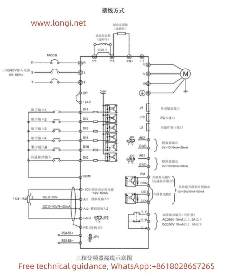
To achieve terminal start/stop and external potentiometer speed adjustment, it is necessary to correctly wire the control terminals of the inverter. Commonly involved terminals include digital input terminals (DI1, DI2, etc.), analog input terminals (AI1, AI2, etc.), and run control terminals (such as RUN, STOP, etc.).
Parameter Settings
- Terminal Start/Stop:
- Set the P0-02 parameter to 1 to select the terminal command channel.
- According to requirements, set DI1, DI2, and other digital input terminals to forward rotation (P4-00=1), reverse rotation (P4-01=2), and stop (e.g., P4-02=3 for the stop terminal in three-wire operation control).
- External Potentiometer Speed Adjustment:
- Set AI1 or AI2 terminals as analog input terminals to receive speed adjustment signals from an external potentiometer.
- Set the P0-03 parameter to the corresponding analog input source (e.g., AI1 or AI2).
- Adjust parameters such as P3-01 (torque boost) and P3-02 (torque boost cutoff frequency) as needed to achieve better speed adjustment performance.
V. Fault Code Meaning Analysis and Troubleshooting Methods
During operation, if the LC400E series inverter encounters a fault, it will immediately stop outputting and display the corresponding fault code. Users can quickly locate the problem and take corresponding measures based on the fault code. Below are the meanings and troubleshooting methods for some common fault codes:
- Err01 (Inverter Unit Protection): Possible causes include output circuit short circuit, module overheat, etc. Solutions include checking and eliminating peripheral faults, cleaning the air duct, replacing the fan, etc.
- Err02 (Acceleration Overcurrent): Possible causes include too short an acceleration time, low voltage, etc. Solutions include increasing the acceleration time, adjusting the voltage to the normal range, etc.
- Err03 (Deceleration Overcurrent): Similar to acceleration overcurrent, possible causes include too short a deceleration time, low voltage, etc. Solutions include adjusting the deceleration time and voltage accordingly.
- Err04 (Constant Speed Overcurrent): Possible causes include sudden load changes during operation, undersized inverter selection, etc. Solutions include eliminating sudden load changes, selecting an inverter with a higher power rating, etc.
In addition, there are various other fault codes, such as Err05 (Acceleration Overvoltage), Err06 (Deceleration Overvoltage), Err07 (Constant Speed Overvoltage), etc. Each fault code corresponds to specific possible causes and solutions. When encountering a fault, users should first refer to the fault information list in the manual for troubleshooting.
VI. Conclusion
The LCGK (ZTV) LC400E series high-performance vector inverter provides users with efficient and reliable automation solutions through its powerful functions and flexible control methods. Through this operation guide, users can better understand and use this series of inverters to achieve more precise and stable control effects. In practical applications, users should also consider specific application scenarios and requirements, reasonably set parameters, and regularly perform maintenance to ensure the long-term stable operation of the inverter.
