
- Introduction to VFD Panel Functions
Panel Composition
The panel of the LS Electric VFD LSLV-S100 series consists of the following main parts:
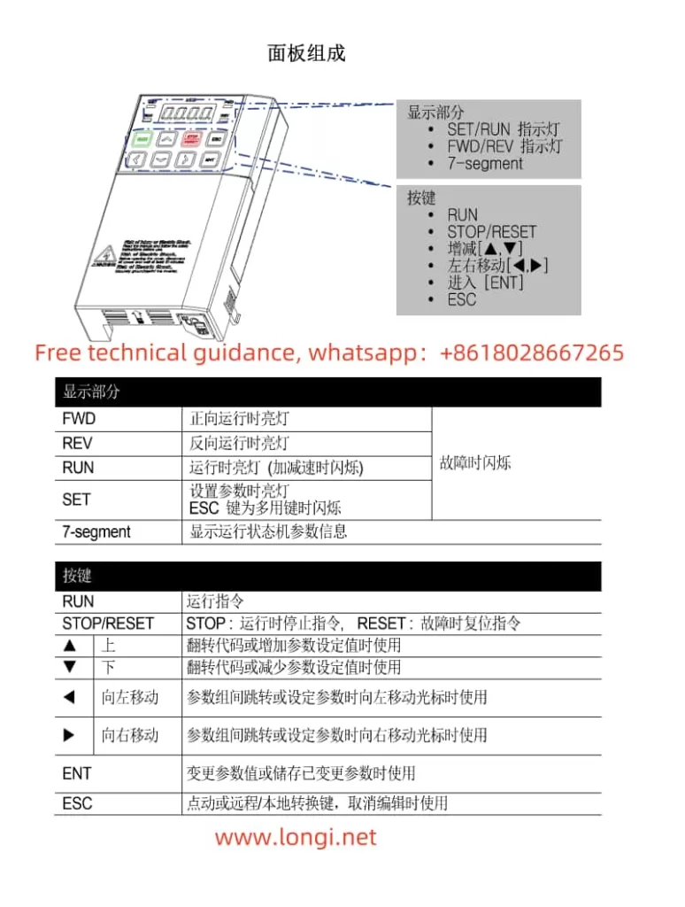
Display: Shows operating status, parameter information, fault indications, etc.
Keys:
RUN: Forward start key; pressing it starts the VFD in forward rotation.
REV: Reverse start key; pressing it starts the VFD in reverse rotation.
STOP/RESET: Stop/reset key; used to stop the VFD or reset faults.
Up/Down Arrow Keys: Used to increase or decrease values during parameter setting.
Left/Right Arrow Keys: Used to navigate between parameter groups or codes.
ENT: Enter key; used to confirm parameter settings or enter a function menu.
ESC: Multi-function key; can be set to move to the initial position, jog operation, switch between local/remote operation, etc.
SET/RUN Indicator: Indicates whether the VFD is in setting mode or running status.
FWD/REV Indicators: Indicate whether the VFD is in forward or reverse rotation, respectively.
Accessing Function Menus
Navigating Parameter Groups: Use the left/right arrow keys to move between different parameter groups.
Parameter Setting: Enter a parameter group, use the up/down arrow keys to select a specific parameter, press ENT to enter editing mode, and press ENT again to confirm the setting.
Jog Operation: If set to jog mode, press the ESC key, and then use the RUN and REV keys for jog operation.
- Terminal Start and Potentiometer Speed Control
Wiring Instructions
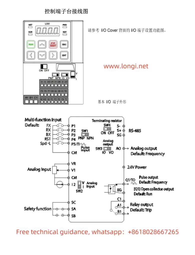
To achieve terminal start and potentiometer speed control, wire as follows:
Forward Start Terminal: Connect the forward start signal (e.g., FX terminal) of the control circuit to the P1 (or specified) terminal of the VFD.
Reverse Start Terminal: Connect the reverse start signal (e.g., RX terminal) of the control circuit to the P2 (or specified) terminal of the VFD.
Stop Terminal: Connect the stop signal of the control circuit to one of the multifunction input terminals of the VFD (e.g., a terminal set for stop function).
Potentiometer Wiring: Connect the three terminals of the potentiometer to the V1 terminal (voltage input), GND (ground), and VR terminal (reference voltage) of the VFD, respectively.
Parameter Setting
Operation Command Method: In the drive group (dr), set the drv parameter to Fx/Rx-1 or Fx/Rx-2 to select the terminal start mode.
Frequency Setting Method: In the basic function group (bA), set the Freq Ref Src parameter to V1 to select potentiometer speed control.
Multifunction Terminal Setting: In the input terminal function group (In), set terminals such as P1, P2 for forward and reverse start functions, and set the required stop terminal for stop function.
- VFD Initialization Setting
To initialize VFD parameters, follow these steps:
Enter the drive group (dr) parameters.
Locate the dr.93 parameter (parameter initialization).
Press ENT to enter editing mode.
Use the up/down arrow keys to set the value to 9 (full initialization).
Press ENT again to confirm the setting.
The VFD will restart and apply the default parameter settings.
- Fault Code Analysis and Solutions
Reading Fault Codes
When a fault occurs in the VFD, a corresponding fault code will be displayed. You can view the fault code on the display of the panel or enter the protection function group (Pr) to view detailed fault information through related parameters.
Common Fault Codes and Solutions
OC (Overcurrent): Check if the motor is overloaded, if the motor cable is short-circuited, or if the output terminals have poor contact.
OV (Overvoltage): Check if the input voltage is too high, if the deceleration time is too short, or if the braking resistor is functioning properly.
UV (Undervoltage): Check if the input power supply is stable and if the voltage is within the allowed range.
OH (Overheat): Check if the ambient temperature around the VFD is too high or if the cooling fan is working normally.
EF (External Fault): Check if the external control circuit is normal or if there is an external fault signal input.
Solutions typically include adjusting parameter settings (e.g., increasing deceleration time, setting appropriate current limits, etc.), checking and repairing wiring issues, and replacing faulty components. When dealing with faults, always disconnect the power supply of the VFD to ensure safety.
This operation guide covers the main panel functions, wiring and parameter settings for terminal start and potentiometer speed control, initialization settings, and fault code analysis and solutions of the LS Electric VFD LSLV-S100 series. We hope this guide helps you better use and maintain this series of VFDs.