Posted on Leave a comment

Ion Pump: Principles, Brand,Applications, and Maintenance

Ion Pump: Principles, Applications, and Maintenance

I. Principles of Ion Pump

The ion pump, a special type of membrane transport protein and reversible ATP enzyme, drives specific ions across the plasma membrane against their electrochemical gradient, consuming energy derived from ATP hydrolysis. This mechanism falls under active transport and plays a crucial role in maintaining ion balance and potential difference across cell membranes.

  1. ATP Hydrolysis: The ion pump catalyzes ATP hydrolysis via its large subunit, releasing energy.
  2. Ion Transport: The hydrolysis products bind to the ion pump, inducing conformational changes that facilitate ion transport. For example, the Na-K pump transports 3 Na⁺ ions outward and 2 K⁺ ions inward per ATP hydrolyzed.
  3. Formation of Electrochemical Gradient: Continuous ion transport by the ion pump establishes a transmembrane electrochemical gradient, vital for cellular physiology.

II. Applications of Ion Pump

The ion pump finds diverse applications in biology experiments, medical treatments, and industrial vacuum technologies.

Biology Experiments:

  • In cell culture, ion pumps maintain ion balance by adjusting ion concentrations in the culture medium.
  • In electrophysiological studies, properties of ion pumps like the Na-K pump are utilized to investigate ion channels and membrane potential changes.

Industrial Vacuum Technology:

  • Sputter ion pumps generate ions through cathode discharge, which are captured upon impacting the cathode, creating a sputtering effect that continuously evacuates gases to maintain a vacuum.
  • Pre-pumping and baking are required before use to expedite gas release and enhance vacuum levels.

III. Common Faults and Repair Methods for Ion Pumps

As high-precision instruments, ion pumps may encounter various faults. Below are common issues and their corresponding repair methods:

Internal Faults:

  • Worn or aged seals: Replace with new seals.
  • Blocked or damaged membranes: Clean or replace the affected membranes.
  • Filter or valve issues: Clean or replace filters and inspect/repair valves.
  • Blocked inlet: Check inlet for patency and clear any debris from inlet pipes and faucet filters.

Power Supply System Faults:

  • Inspect power plug and cable connections for proper attachment and ensure stable power voltage.

Target End Leakage or Burnout:

  • Check target end pump operation and use methods such as power plug swapping and monitoring pump body temperature to assess pump status.
  • In case of burnout, which may result from excessive plate load, attempt to restore pump function using methods like tapping.

Insufficient Vacuum:

  • Verify adequate pre-pump vacuum levels and adjust pre-pumping duration and baking temperature.
  • Check ion pump controller settings to ensure correct discharge current and voltage.

IV. Major Ion Pump Models

  1. Agilent Technologies:
    • VacIon Plus Series: VacIon Plus 20, VacIon Plus 40, VacIon Plus 55, VacIon Plus 75, VacIon Plus 150
  2. Gamma Vacuum:
    • StarCell Series: 20S, 55S, 100S, 300S
    • Titan Series: Titan 20, Titan 55, Titan 100, Titan 300
  3. Duniway Stockroom Corporation:
    • NexTorr Series: NexTorr D100-5, NexTorr D200-10
    • Standard Series: Duniway IP-20, Duniway IP-40, Duniway IP-60
  4. SAES Getters:
    • NEXTorr Series: NEXTorr D 100-5, NEXTorr D 200-10, NEXTorr Z 200-10
    • CapaciTorr Series: CapaciTorr D 200, CapaciTorr D 400
  5. Varian:
    • StarCell Series: 20 StarCell, 40 StarCell, 55 StarCell, 75 StarCell, 150 StarCell
  6. Agilent Varian:
    • Ion Pump Controller: PCMini, IPC3, IPC6
  7. Gamma ION:
    • Classic Series: 20I, 40I, 55I, 75I, 150I
  8. TeraVac:
    • Ultra Series: 20U, 40U, 55U, 75U, 150U
  9. Pfeiffer Vacuum:
    • HiPace Series: HiPace 300, HiPace 700
    • DigiLine Series: DigiLine Pascal 2021, DigiLine Pascal 2002
  10. Riber:
    • Riber Ion Pump Series: IP 20, IP 40, IP 60

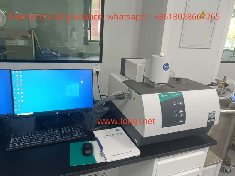
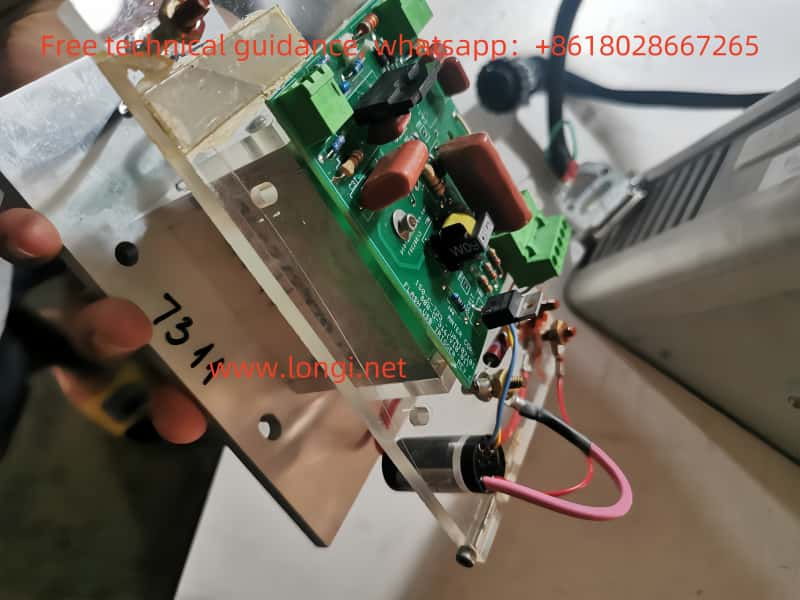
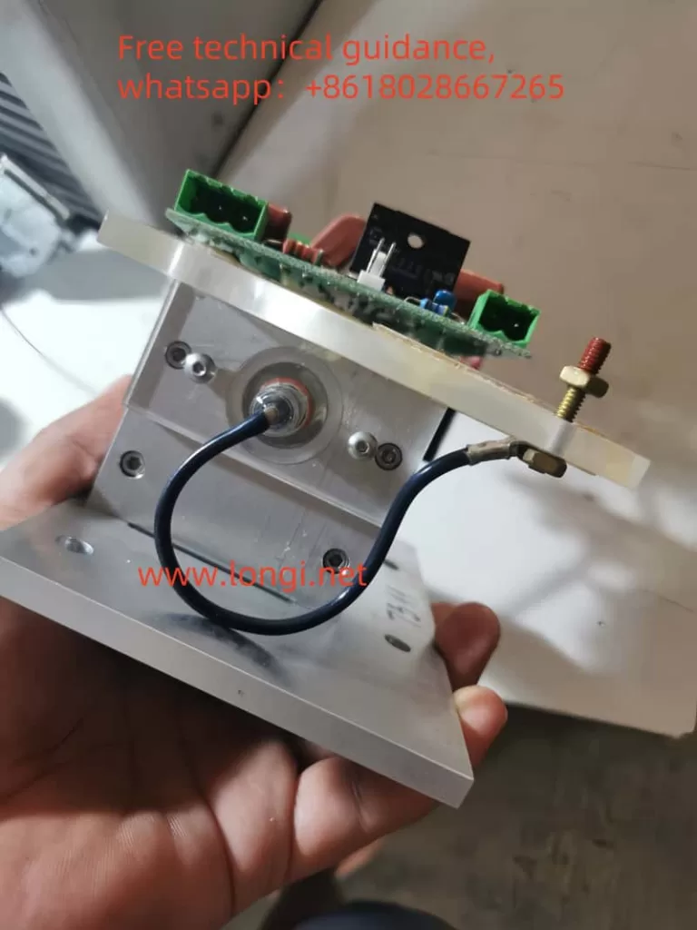
Longi Electromechanical Company specializes in the repair and maintenance of ion pumps and controllers, with nearly 30 years of experience. We offer prompt repairs for various instruments and also engage in the recycling and sales of ion pumps and controllers. Feel free to contact us for more information.

Posted on Leave a comment

 Comprehensive Guide to Fluorescence Analyzer: Usage, Faults, and Repair Methods

I. Overview and Basic Principles of Fluorescence Analyzer

A fluorescence analyzer is a precision instrument that utilizes the fluorescence phenomenon of substances under specific excitation conditions to analyze sample composition and properties. When chemical substances in a sample are irradiated by light of a specific wavelength, they absorb energy, transition to a high-energy state, and subsequently return to the ground state while releasing photons, producing fluorescence. By measuring the intensity and characteristic spectrum of fluorescence, the fluorescence analyzer can precisely analyze the composition and structure of the sample.

II. Usage Method of Fluorescence Analyzer

Startup Preparation:

  • Ensure that external equipment such as air compressors, water chillers, and gas supply systems are operating normally.
  • Turn on the fluorescence analyzer host and computer, and run the analysis software.

Sample Preparation:

  • Prepare samples according to experimental requirements, ensuring sample purity and compatibility with reagents.
  • Place the sample in an appropriate container for testing.

Instrument Calibration:

  • Perform zero-point calibration to ensure accurate measurements.
  • Adjust instrument parameters as needed, such as excitation wavelength and emission wavelength.

Sample Testing:

  • Place the sample in the sample chamber of the fluorescence analyzer.
  • Initiate the testing program and wait for the instrument to complete the measurement of the fluorescence spectrum.
  • Record and analyze the fluorescence spectrum data to draw conclusions about the sample’s composition and properties.

Shutdown and Cleaning:

  • After testing, turn off the fluorescence analyzer host and computer.
  • Clean the sample chamber and the exterior of the instrument to ensure it is in good condition.

III. Types of Faults and Repair Methods for Fluorescence Analyzer

Unstable Fluorescence Intensity:

  • Causes: Aging of the lamp filament, dirty electrodes, environmental temperature fluctuations.
  • Repair Methods: Replace the lamp filament, clean the electrodes, stabilize the environmental temperature.

Decreased Sensitivity:

  • Causes: Expired reagents, incompatibility between sample and reagent, contamination of the optical path system.
  • Repair Methods: Replace with fresh reagents, test using the same type of sample, clean the optical path system.

Instrument Failure to Turn On:

  • Causes: Power supply failure, connection issues between the computer and host, software system errors.
  • Repair Methods: Check the power supply, reconnect the computer and host, restart the software system or contact the manufacturer for repairs.

Low Water Flow or Water Circuit Blockage:

  • Causes: Water filter blockage or impurities in the water circuit system.
  • Repair Methods: Clean or replace the water filter, inspect and clear impurities in the water circuit system.

IV. Repair Precautions

  • Before performing any repair operations, be sure to turn off the instrument’s power supply to ensure safety.
  • Use professional tools for disassembly and installation to avoid damaging instrument components.
  • Follow the manufacturer’s repair manuals and guides to ensure correct repair procedures.
  • For complex faults or issues that cannot be resolved independently, promptly contact professional repair personnel from Rongji Electromechanical Company.

V. Conclusion

As a high-precision analytical instrument, the fluorescence analyzer plays a crucial role in scientific research and production fields. Through this introduction, we have gained an understanding of the basic principles, usage methods, common fault types, and repair methods of the fluorescence analyzer. We hope that this information will help you better use and maintain the fluorescence analyzer, thereby improving research and production efficiency.

VI. Brands and Models of Fluorescence Analyzers Repaired by Rongji Electromechanical Company

  1. Thermo Fisher Scientific
    • Fluoroskan FL: Microplate Fluorometer
    • NanoDrop 3300: Micro-Volume Fluorospectrometer
    • Lumina Fluorescence Spectrometer: General Fluorescence Spectrometer
  2. Agilent Technologies
    • Cary Eclipse: Fluorescence Spectrometer
    • Agilent 4300 Handheld FTIR: Handheld Fluorescence Analyzer
  3. PerkinElmer
    • LS 55: Fluorescence Spectrometer
    • EnVision: Multimode Microplate Reader
    • Victor Nivo: Multimode Microplate Reader
  4. Horiba Scientific
    • FluoroMax-4: Fluorescence Spectrometer
    • FluoroMax Plus: High-Performance Fluorescence Spectrometer
    • Aqualog: Water Quality Analysis Fluorescence Spectrometer
  5. Shimadzu
    • RF-6000: High-Sensitivity Fluorescence Spectrometer
    • RF-5301PC: Fluorescence Spectrometer
  6. Edinburgh Instruments
    • FLS1000: Fluorescence Spectrometer
    • FS5: Fluorescence Spectrometer
    • Mini-tau: Fluorescence Lifetime System
  7. Hitachi
    • F-7000: Fluorescence Spectrometer
    • F-7100: High-Performance Fluorescence Spectrometer
    • F-2700: Compact Fluorescence Spectrometer
  8. Zeiss
    • LSM 880: Laser Scanning Confocal Microscope with Fluorescence Analysis Function
    • Axio Imager: Fluorescence Microscope
  9. Bruker
    • FOCUS-G: Portable Fluorescence Spectrometer
    • CRYO-G: Fluorescence Lifetime Microscope
  10. Tecan
    • Spark: Multimode Microplate Reader with Fluorescence Analysis Function
    • Infinite 200 PRO: Multimode Microplate Reader
  11. BioTek (Agilent)
    • Cytation 5: Multimode Microplate Reader and Imaging System
    • Synergy H1: Multimode Microplate Reader
  12. Molecular Devices
    • SpectraMax i3x: Multimode Microplate Reader
    • FlexStation 3: Fluorescence Analysis System
  13. Photon Technology International (PTI)
    • QuantaMaster 8000: Fluorescence Spectrometer
    • TimeMaster: Fluorescence Lifetime System
  14. Jobin Yvon (Horiba)
    • FluoroLog: Fluorescence Spectrometer
    • FluoroCube: Fluorescence Lifetime System

Rongji Electromechanical Company has nearly 30 years of experience in repairing fluorescence analyzers (fluorospectrometers, atomic fluorescence spectrometers) and can quickly repair various types of instruments. Additionally, we recycle and sell various used fluorescence analyzers. Please feel free to consult us.

Posted on Leave a comment

Comprehensive Guide to Fluorescence Analyzer: Operating Procedures, Faults, and Repair Methods

I. Overview and Basic Principles of Fluorescence Analyzer

The fluorescence analyzer is a precise instrument that utilizes the fluorescence phenomenon of substances under specific excitation conditions to analyze sample composition and properties. When chemicals in a sample are irradiated by light of a specific wavelength, they absorb energy, transition to a higher energy state, and subsequently return to the ground state while releasing photons, producing fluorescence. By measuring the intensity and characteristic spectrum of fluorescence, the fluorescence analyzer can accurately analyze the composition and structure of the sample.

II. Operating Procedures for Fluorescence Analyzer

Startup Preparation:

  • Ensure the normal operation of external equipment such as air compressor, water cooler, and gas supply system.
  • Turn on the fluorescence analyzer host and computer, and run the analysis software.

Sample Preparation:

  • Prepare samples according to experimental requirements, ensuring sample purity and compatibility with reagents.
  • Place the sample in an appropriate container for testing.

Instrument Calibration:

  • Perform zero-point calibration to ensure accurate measurements.
  • Adjust instrument parameters as needed, such as excitation wavelength and emission wavelength.

Sample Testing:

  • Place the sample in the sample chamber of the fluorescence analyzer.
  • Initiate the testing program and wait for the instrument to complete the measurement of the fluorescence spectrum.
  • Record and analyze the fluorescence spectrum data to draw conclusions about the sample’s composition and properties.

Shutdown and Cleaning:

  • After testing, turn off the fluorescence analyzer host and computer.
  • Clean the sample chamber and the exterior of the instrument to maintain its good condition.

III. Types of Faults and Repair Methods for Fluorescence Analyzer

Unstable Fluorescence Intensity:

  • Causes: Aging of lamp filament, dirty electrodes, fluctuations in ambient temperature.
  • Repair Methods: Replace the lamp filament, clean the electrodes, stabilize the ambient temperature.

Decreased Sensitivity:

  • Causes: Expired reagents, incompatibility between sample and reagent, contamination of the optical path system.
  • Repair Methods: Replace with fresh reagents, test using the same type of sample, clean the optical path system.

Instrument Failure to Turn On:

  • Causes: Power supply failure, connection issues between computer and host, software system errors.
  • Repair Methods: Check the power supply, reconnect the computer and host, restart the software system or contact the manufacturer for repair.

Low Water Flow or Water Circuit Blockage:

  • Causes: Blocked water filter or impurities in the water circuit system.
  • Repair Methods: Clean or replace the water filter, inspect and clear impurities in the water circuit system.

IV. Repair Precautions

  • Before performing any repair operations, be sure to turn off the instrument’s power supply to ensure safety.
  • Use professional tools for disassembly and installation to avoid damaging instrument components.
  • Follow the repair manuals and guides provided by the manufacturer to ensure correct repair procedures.
  • For complex faults or issues that cannot be resolved independently, promptly contact professional repair personnel from Rongji Electromechanical Company.

V. Conclusion

As a high-precision analytical instrument, the fluorescence analyzer plays a crucial role in scientific research and production fields. Through this introduction, we have gained an understanding of the basic principles, usage methods, common fault types, and repair methods of the fluorescence analyzer. We hope that this information will help you better use and maintain the fluorescence analyzer, thereby improving research and production efficiency.

VI. Brands and Models of Fluorescence Analyzers Repaired by Rongji Electromechanical Company

  1. Thermo Fisher Scientific
    • Fluoroskan FL: Microplate Fluorometer
    • NanoDrop 3300: Micro-Volume Fluorometer
    • Lumina Fluorescence Spectrometer: General Fluorescence Spectrometer
  2. Agilent Technologies
    • Cary Eclipse: Fluorescence Spectrometer
    • Agilent 4300 Handheld FTIR: Handheld Fluorescence Analyzer
  3. PerkinElmer
    • LS 55: Fluorescence Spectrometer
    • EnVision: Multimode Microplate Reader
    • Victor Nivo: Multimode Microplate Reader
  4. Horiba Scientific
    • FluoroMax-4: Fluorescence Spectrometer
    • FluoroMax Plus: High-Performance Fluorescence Spectrometer
    • Aqualog: Water Quality Analysis Fluorescence Spectrometer
  5. Shimadzu
    • RF-6000: High-Sensitivity Fluorescence Spectrometer
    • RF-5301PC: Fluorescence Spectrometer
  6. Edinburgh Instruments
    • FLS1000: Fluorescence Spectrometer
    • FS5: Fluorescence Spectrometer
    • Mini-tau: Fluorescence Lifetime System
  7. Hitachi
    • F-7000: Fluorescence Spectrometer
    • F-7100: High-Performance Fluorescence Spectrometer
    • F-2700: Compact Fluorescence Spectrometer
  8. Zeiss
    • LSM 880: Laser Scanning Confocal Microscope with Fluorescence Analysis Function
    • Axio Imager: Fluorescence Microscope
  9. Bruker
    • FOCUS-G: Portable Fluorescence Spectrometer
    • CRYO-G: Fluorescence Lifetime Microscope
  10. Tecan
    • Spark: Multimode Microplate Reader with Fluorescence Analysis Function
    • Infinite 200 PRO: Multimode Microplate Reader
  11. BioTek (Agilent)
    • Cytation 5: Multimode Microplate Reader and Imaging System
    • Synergy H1: Multimode Microplate Reader
  12. Molecular Devices
    • SpectraMax i3x: Multimode Microplate Reader
    • FlexStation 3: Fluorescence Analysis System
  13. Photon Technology International (PTI)
    • QuantaMaster 8000: Fluorescence Spectrometer
    • TimeMaster: Fluorescence Lifetime System
  14. Jobin Yvon (Horiba)
    • FluoroLog: Fluorescence Spectrometer
    • FluoroCube: Fluorescence Lifetime System

Rongji Electromechanical Company has nearly 30 years of experience in repairing fluorescence analyzers (fluorescence spectrometers, atomic fluorescence spectrometers) and can quickly repair various types of instruments. Additionally, we recycle and sell various used fluorescence analyzers. Welcome to consult.

Posted on Leave a comment

 Dual-Frequency Laser Interferometer: Principles, Usage, Maintenance, Repair, and Brands Overvie

I. Principles of Dual-Frequency Laser Interferometer

The dual-frequency laser interferometer, an advanced measurement instrument based on heterodyne interference principles, evolves from the single-frequency laser interferometer. It utilizes two laser beams of different frequencies for interference measurement, achieving high-precision measurement of various physical quantities such as displacement, length, and angle. This instrument finds wide application in precision machining, metrological inspection, and scientific research, serving as a crucial tool for enhancing equipment accuracy and detection efficiency.

Working Principles:

  • Based on the Zeeman splitting effect and frequency pulling effect.
  • A magnetic field of approximately 0.03 Tesla is applied to a He-Ne laser, generating left- and right-handed circularly polarized light with two different frequencies (f1 and f2).
  • After processing through a series of optical elements, these beams are split into reference and measurement beams.
  • When the movable mirror shifts, the frequency of the measurement beam changes (f2 ± Δf) due to the Doppler effect, while the reference beam’s frequency remains constant.
  • The two beams interfere on a photodetector, producing an electrical signal containing the frequency difference Δf. By counting the changes in frequency difference, the displacement of the movable mirror can be calculated.

Key Components:

  • Laser Source: Employs a laser, such as a He-Ne laser or semiconductor laser, to generate two laser beams with different frequencies.
  • Optical Beam Splitting: The laser beam is divided into two beams by a beam splitter, one serving as the reference beam and the other as the measurement beam.
  • Optical Path Design: The reference beam follows a fixed path, while the measurement beam traverses a variable path. The two beams recombine in the interferometer, producing interference fringes.
  • Interference Fringes: The movement of interference fringes reflects changes in the length of the measurement path. Precise calculations of the displacement or length changes of the measured object can be derived by analyzing these fringes.
  • Signal Processing: The interference fringe signal is converted into an electrical signal by a photodetector and processed to obtain measurement results.

II. Usage Instructions

  1. System Connection: Connect the laptop, laser interferometer, environmental compensation unit, printer, etc., via communication cables and power them on.
  2. Laser Warm-up: Turn on the laser interferometer and allow it to warm up for about 15-20 minutes. Proceed with measurements once the laser is stable (indicator light turns green).
  3. Software Initialization: Start the measurement software on the laptop and enter the corresponding measurement subroutine.
  4. Optical Mirror Installation: Secure the laser interferometer, reflectors, beam splitters, and other optical components on the measurement tripod and machine tool in appropriate positions, and adjust for alignment.
  5. Target Value Setting: Set target values according to measurement requirements and program the CNC measurement procedure.
  6. Data Collection: Initiate the data collection program for automatic or manual data acquisition and monitor the measurement data.

III. Common Faults and Repair Methods

  1. Laser Fault:
    • Symptom: Laser does not emit light or has insufficient intensity.
    • Repair: Check the laser power supply and connection cables, ensuring proper power supply. Replace the laser if necessary.
  2. Optical Path Deviation:
    • Symptom: Interference fringes are unclear or disappear.
    • Repair: Adjust the positions of the beam splitter and reflector to ensure parallel optical paths and accurate beam convergence points.
  3. Photodetector Fault:
    • Symptom: Signal is unstable or there is no signal output.
    • Repair: Check the detector’s power supply and connection cables, clean the detector surface to ensure normal operation.
  4. Environmental Interference:
    • Symptom: Measurement results are highly variable or inaccurate.
    • Repair: Isolate the instrument from environmental vibrations and temperature changes, ensuring a stable working environment.
  5. Signal Processor Fault:
    • Symptom: Data collection is unstable or analysis results are erroneous.
    • Repair: Check signal processor connections and software settings, reinstall or update software if necessary.

IV. Precautions and Maintenance

  • Environmental Requirements: Place the instrument in a dry, clean, and vibration-free environment, avoiding the impact of moisture and dust on optical components.
  • Handling and Storage: Hold the base when moving the instrument to prevent guide rail deformation; store optical components in a clean and dry container when not in use.
  • Cleaning and Lubrication: Avoid wiping mirrors and beam splitters unless necessary, using scientific methods for cleaning; regularly lubricate moving parts to maintain good working condition.
  • Usage Norms: Avoid forced rotation, hard pulling, and other improper operations; apply appropriate force to each adjustment component.

V. Brands and Models of Dual-Frequency Laser Interferometers Repaired by Longi Electromechanical Company

  1. Renishaw
    • XL-80: High-precision laser interferometer system
    • HS20: Dual-frequency laser interferometer for large-range position measurement
  2. Keysight Technologies (formerly Agilent Technologies)
    • 5519A/B: Dual-frequency laser interferometer for high-precision positioning and measurement
    • 5530: Laser interferometer system supporting various measurement applications
  3. Zygo Corporation
    • ZMI 4000 Series: Dual-frequency laser interferometer for high-precision position and speed measurement (ZMI 4500, ZMI 4100)
    • ZMI 2000 Series: High-performance dual-frequency laser interferometer (ZMI 2400, ZMI 2002)
  4. SIOS Messtechnik
    • SP 2000 Series: Dual-frequency laser interferometer system for precise length and angle measurement (SP 2000, SP 2000 TR)
    • SP 5000 Series: High-resolution dual-frequency laser interferometer (SP 5000 NG, SP 5000 TR)
  5. Hamar Laser Instruments
    • L-730 Series: Dual-frequency laser interferometer for machine calibration and alignment (L-730, L-740)
    • L-750 Series: High-precision dual-frequency laser interferometer (L-750)
  6. API (Automated Precision Inc.)
    • XD Series: High-precision laser interferometer system (XD6, XD8)
  7. Renishaw/Anorad (Collaborative Brand)
    • RLE Series: High-performance laser interferometer (RLE10, RLE20)
  8. Mahr Metrology
    • MarForm MFU Series: High-precision laser interferometer for shape measurement and surface contour measurement (MFU 100, MFU 200)
  9. Mitutoyo
    • Laser 20: Dual-frequency laser interferometer for high-precision position measurement
    • Laser 30: High-performance dual-frequency laser interferometer
  10. Status Pro
    • EZ-EL Series: High-precision laser interferometer system (EZ-EL-A, EZ-EL-B)
  11. Tokyo Seimitsu
    • LV-50
  12. Marposs
    • BLU Series:
      • BLU LT: For length and displacement measurement
      • BLU LI: For straightness and angle measurement

Longi Electromechanical Company specializes in the repair of dual-frequency laser interferometers, with nearly 30 years of experience. We can quickly repair various instruments and also offer the recycling and sale of used dual-frequency laser interferometers. Welcome to consult us.

Posted on Leave a comment

Comprehensive Guide to Mass Spectrometers: Principles, Usage, Maintenance, and Brands Serviced

I. Functional Principle of Mass Spectrometer

The mass spectrometer, a highly precise scientific instrument, is primarily used to determine the composition and structure of samples. Its operating principle encompasses the following steps:

  1. Sample Ionization: Sample molecules are ionized into positively or negatively charged ions in the ion source.
  2. Mass Separation: The generated ions are accelerated and transmitted to the mass analyzer, where they are separated based on their mass-to-charge ratio (m/z).
  3. Detection and Recording: The separated ions enter the detector, producing signals that are recorded to form a mass spectrum.
  4. Data Analysis: By analyzing the mass spectrum, information such as the composition, structure, and relative abundance of the sample can be determined.

The core components of a mass spectrometer include the ion source, mass analyzer, and detector, all housed within a vacuum system to ensure analytical accuracy.

II. Usage Method of Mass Spectrometer

Usage methods may vary by model and manufacturer, but generally include the following steps:

Preparation:

  • Safety check: Ensure laboratory safety and use personal protective equipment.
  • Sample preparation: Dissolve the sample in an appropriate solvent and clean it to remove impurities.
  • Select the ion source and adjust ionization parameters.
  • Choose the analysis mode and adjust mass spectrometer parameters.

Startup:

  • Turn on the gas supply and mechanical pump, and after achieving the required vacuum, turn on the molecular turbo pump.
  • Perform calibration to ensure optimal mass spectrometer performance.

Analysis:

  • Start the mass spectrometer, observe the mass spectrum, and record corresponding peaks.
  • Analyze the position, intensity, and shape of peaks for mass analysis.
  • Identify compounds in the sample.

Shutdown:

  • Stop the mass spectrometer operation.
  • Flush the system to prevent cross-contamination.
  • Turn off the mass spectrometer and disconnect the power supply.

III. Common Faults and Repair Methods

Common faults and their repair methods include:

  1. Unstable Power Supply:
    • Fault manifestation: Voltage fluctuations, unstable current supply, or sudden power outages and restarts.
    • Repair method: Check power lines and modules, ensure proper grounding, and replace damaged power components.
  2. Aging or Damage of Power Modules:
    • Fault manifestation: Decreased power output performance, insufficient energy for the ion source.
    • Repair method: Replace aged power modules and ensure normal operation of high-voltage components.
  3. Poor Grounding or Contact Issues with Power Lines:
    • Fault manifestation: Increased power noise, interference with signal acquisition, resulting in false peaks or abnormal peak intensities.
    • Repair method: Check grounding and power line connections, ensure good contact, and reduce power noise.
  4. Failure of Power Cooling System:
    • Fault manifestation: Overheating of power supply, leading to drifting output parameters and shortened lifespan.
    • Repair method: Check the cooling system, ensure proper heat dissipation, and replace cooling fans or radiators if necessary.
  5. Failure of Mechanical and Molecular Turbo Pumps:
    • Fault manifestation: Insufficient vacuum, affecting mass spectrometry accuracy.
    • Repair method: Regularly clean and replace mechanical pump oil, check the status of molecular turbo pumps, and repair or replace as needed.
  6. Contamination or Damage of Ion Source:
    • Fault manifestation: Reduced ionization efficiency, poor mass spectrum peak shapes.
    • Repair method: Regularly clean the ion source chamber and sampling cone, and replace damaged ion source components.

IV. Precautions

When using a mass spectrometer, follow laboratory safety regulations and use personal protective equipment. Adjust analysis parameters based on sample properties and mass spectrometer model for optimal results. Regularly perform performance verification and maintenance to ensure long-term efficient operation of the mass spectrometer.

V. Brands and Models of Mass Spectrometers Serviced by Longi Electromechanical

  1. Thermo Fisher Scientific:
    • Orbitrap Series: Orbitrap Exploris 480, Orbitrap Eclipse, Orbitrap Elite, Orbitrap Fusion Lumos
    • Q Exactive Series: Q Exactive, Q Exactive HF, Q Exactive HF-X, Q Exactive Plus
    • TSQ Series: TSQ Altis, TSQ Quantis, TSQ Endura
    • LTQ Series: LTQ Orbitrap XL, LTQ XL
  2. Agilent Technologies:
    • 6500 Series: 6530 Q-TOF, 6546 Q-TOF, 6550 iFunnel Q-TOF, 6560 Ion Mobility Q-TOF
    • 6100 Series: 6130 Quadrupole LC/MS, 6140 Quadrupole LC/MS
    • 7000 Series: 7010 Triple Quadrupole GC/MS, 7000D Triple Quadrupole GC/MS
    • 7700 Series: 7700x ICP-MS
  3. Waters Corporation:
    • Xevo Series: Xevo G2-XS QTof, Xevo TQ-S, Xevo TQ-XS
    • Synapt Series: Synapt G2-Si, Synapt XS, Vion IMS QTof, ACQUITY RDa
  4. Bruker:
    • timsTOF Series: timsTOF Pro, timsTOF fleX
    • MALDI-TOF Series: ultrafleXtreme, autoflex maX
    • ESI-QTOF Series: Impact II, maXis II, scimaX
  5. Sciex (AB Sciex):
    • TripleTOF Series: TripleTOF 6600, TripleTOF 5600+
    • QTRAP Series: QTRAP 6500+, QTRAP 5500, QTRAP 4500
    • Triple Quad Series: Triple Quad 7500, Triple Quad 6500+, Triple Quad 5500
  6. PerkinElmer:
    • Flexar Series: Flexar SQ 300 MS, Flexar TOF MS
    • Clarus Series: Clarus SQ 8 GC/MS
  7. Shimadzu:
    • LCMS Series: LCMS-8045, LCMS-8050, LCMS-8060
    • GCMS Series: GCMS-TQ8050 NX, GCMS-QP2010 Ultra, GCMS-QP2020 NX
  8. JEOL:
    • AccuTOF Series: AccuTOF DART, AccuTOF GCx, JMS-T100LC
  9. LECO:
    • Pegasus Series: Pegasus BT, Pegasus GC-HRT 4D, Pegasus BT 4D
    • TruTOF Series
  10. Hitachi: NanoFrontier LD, Chromaster

Longi Electromechanical has nearly 30 years of experience in repairing mass spectrometers, enabling quick repairs for various instruments. Additionally, we recycle and sell used mass spectrometers. Welcome to consult.

Posted on Leave a comment

Operation, Brand,Maintenance, and Troubleshooting of Centrifuges: A Comprehensive Guide

Introduction

A centrifuge is a device that utilizes centrifugal force to separate different components in a mixture. Its working principle is based on Newton’s second law, where the centrifugal force experienced by an object during rotation is proportional to the square of the angular velocity and the radius of rotation, and also proportional to the mass of the object. In a centrifuge, substances are placed on a rotating turntable and accelerated along with it. As the rotation speed increases, the substances experience centrifugal force, leading to their separation into different components. Factors such as the rotation speed, turntable diameter, and turntable material of the centrifuge all influence the magnitude of the centrifugal force and the effectiveness of the separation.

I. Operation Method of the Centrifuge

The operation of a centrifuge generally involves the following steps:

Preparation Stage:

  • Check if the centrifuge is in normal working condition.
  • Prepare necessary centrifuge tubes, turntables, and other accessories.

Loading Samples:

  • Place the substances to be separated into centrifuge tubes.
  • Position the centrifuge tubes on the turntable of the centrifuge, ensuring they are correctly placed and evenly distributed to maintain balance.

Setting Parameters:

  • Set the parameters of the centrifuge, such as rotation speed and centrifugation time, according to the separation requirements and sample characteristics.

Starting the Centrifuge:

  • Press the start button to initiate the centrifuge.

Monitoring the Centrifuge:

  • Monitor the running status of the centrifuge during operation to ensure the centrifugation process proceeds normally.

Stopping the Centrifuge:

  • After centrifugation is complete, press the stop button, halt the centrifuge, and retrieve the separated substances.

II. Common Faults and Troubleshooting Methods for the Centrifuge

The centrifuge may encounter various faults during use. Below are some common faults and their troubleshooting methods:

  • Unbalanced Centrifuge or Uneven Placement of Centrifuge Tubes:
    • Adjust the level of the centrifuge to ensure it is stable.
    • Evenly distribute the centrifuge tubes to avoid imbalance caused by uneven weight distribution.
  • Loose or Damaged Rotor:
    • Check if the rotor is loose or damaged, and replace it if necessary.
  • Loose Screws, Worn Bearings, or Motor Faults:
    • Tighten the screws of the centrifuge.
    • Check for bearing wear and replace if necessary.
    • Check for motor faults and repair or replace if needed.
  • Blocked Oil Filter or Oil Leakage:
    • Inspect the oil filter, oil pipes, and connectors to ensure they are unblocked.
    • Check for oil leakage and repair promptly if found.
  • Power Issues or Damaged Circuit Board:
    • Check if the power plug is properly inserted and the power cord is energized.
    • Check if the fuse is burned out and try replacing it.
    • If the above are normal, the circuit board may be damaged and needs to be returned for repair or replacement.
  • Water Circuit Issues or Damaged Seal Rings:
    • Check if the water circuit is unblocked and the solenoid valve is functioning properly.
    • Inspect the seal rings for damage or impurities and replace if necessary.

III. Maintenance Methods for the Centrifuge

The maintenance of a centrifuge mainly includes the following steps:

  • Cleaning:
    • Regularly clean the centrifuge to remove accumulated dirt and residues, restoring the design dimensions of the cavity.
  • Inspection:
    • Regularly inspect various components of the centrifuge, including feed pipes, drums, spirals, housing, frames, and motors, to ensure they are in normal structure and working condition.
  • Calibration:
    • Regularly calibrate the assembly components of the centrifuge to ensure good dynamic balance.
  • Lubrication:
    • Regularly lubricate the bearings, gears, and other components of the centrifuge to reduce wear and extend service life.
  • Maintenance:
    • Regularly maintain the centrifuge, including replacing worn components and cleaning internal dirt.
  • Fault Diagnosis:
    • Promptly diagnose the cause of any faults in the centrifuge through methods such as listening to sounds, checking the power supply, and viewing fault codes on the display. Seek professional assistance if unable to resolve.

IV. Centrifuge Brands and Models Repaired by Longi Electromechanical Company

  1. Beckman Coulter:
    • Avanti JXN-30
    • Avanti JXN-26
    • Allegra X-30 Series
    • Allegra V-15R
    • Microfuge 20 Series
    • Optima XE/XPN Series (XE/XPN-90, XE/XPN-100, XE/XPN-80)
  2. Thermo Fisher Scientific:
    • Sorvall LYNX 6000
    • Sorvall Legend X1/X1R
    • Sorvall ST 16/ST 16R
    • Sorvall RC 6 Plus
    • Sorvall Evolution RC
    • Sorvall BIOS 16
    • Sorvall WX+ Ultracentrifuge Series (WX Ultra 80, WX Ultra 90, WX Ultra 100)
  3. Eppendorf:
    • 5810/5810 R
    • 5910/5910 R
    • 5424/5424 R
    • 5430/5430 R
    • 5804/5804 R
    • Centrifuge 5920 R
    • Centrifuge 5702/5702 R
  4. Hettich:
    • Rotina 420/420R
    • Rotofix 32A
    • Rotina 380/380R
    • Universal 320/320R
    • EBA 200/200S
    • Mikro 200/200R
  5. Sigma:
    • Sigma 8K
    • Sigma 6-16 KS
    • Sigma 3-30KS
    • Sigma 2-16K
    • Sigma 1-14
    • Sigma 4-5L
    • Sigma 3-18KS
  6. Sorvall:
    • Sorvall RC-5B Plus
    • Sorvall RC 12BP Plus
    • Sorvall Legend XTR/X1R
    • Sorvall MTX 150
    • Sorvall RC-6 Plus
  7. Beckman Optima:
    • Optima MAX-XP
    • Optima MAX-TL
    • Optima XPN/XE
  8. Hitachi:
    • Himac CR21GIII
    • Himac CS150FNX
    • Himac CR30NX
  9. HERMLE:
    • Z36HK
    • Z446
    • Z326
    • Z216MK
  10. Thermo Sorvall:
    • Thermo Sorvall LYNX 4000/6000
    • Thermo Sorvall WX 80/90/100 Ultra Series
  11. KENDRO (Acquired by Thermo Fisher):
    • High-Efficiency Centrifuges: Sorvall RC-6 Plus, Sorvall RC-5C Plus, Sorvall RC-3BP Plus
    • Ultrahigh-Speed Centrifuges: WX Ultra 80, WX Ultra 90, WX Ultra 100
    • Benchtop Centrifuges: Heraeus Multifuge X3/X3R, Heraeus Megafuge 8/8R
    • Microcentrifuges: Heraeus Pico 21/Pico 21R, Heraeus Fresco 17/Fresco 17R
    • Multifunctional Centrifuges: Sorvall Legend X1/X1R, Sorvall Legend XT/XTR
  12. Hunan Xiangyi:
    • CH210
    • CHT210R
    • HT150R
    • HT165R
    • HT200
    • HT200R
    • H2050R

Conclusion

Longii Electromechanical Company has nearly 30 years of experience in repairing centrifuges and can quickly repair various instruments. Additionally, we recycle and sell various used centrifuges. Welcome to consult with us.

Posted on Leave a comment

Working Principle, Operation, and Maintenance of Dispensing Machines

Working Principle and Operation of Dispensing Machines

Working Principle:
Dispensing machines primarily utilize compressed air or pressure systems to transfer adhesive from the reservoir to the dispensing nozzle, with precise control of adhesive flow rate and direction achieved through control valves. During operation, the machine applies adhesive accurately onto workpieces at predetermined positions and shapes, based on preset parameters such as adhesive flow rate, speed, duration, and the machine’s movement path.


I. Usage of Dispensing Machines

  1. Preparing Adhesive:
    • Inject adhesive into the reservoir and secure it onto the machine.
  2. Setting Parameters:
    • Configure the machine’s working parameters, including adhesive flow rate, speed, and duration, as required.
  3. Placing Workpieces:
    • Position the workpiece requiring adhesive on the machine’s workbench and secure it in place.
  4. Starting Up and Setting:
    • Turn on the dispensing machine’s power switch and, following the instructions on the operation panel or touchscreen, set the dispensing position and shape for the workpiece.
  5. Checking and Starting:
    • Verify that the adhesive flow rate and workbench movement speed meet requirements, then start dispensing to ensure uniform application of adhesive on the workpiece.
  6. Ending and Cleaning:
    • After dispensing, turn off the machine’s power switch and clean the machine, dispensing nozzle, and other components to prevent adhesive from drying and causing blockages.

II. Common Faults and Repair Methods

  1. Nozzle Blockage:
    • Cause: Incomplete cleaning of the adhesive valve or needle, impurities in the adhesive, or mixing of incompatible adhesives.
    • Solution: Replace with a clean needle, use higher-quality adhesive, and clean the adhesive valve promptly.
  2. Adhesive Valve Dripping or Leakage:
    • Cause: Needle diameter too small, affecting bubble venting, leading to backpressure and post-dispensing dripping.
    • Solution: Replace with a larger needle, add a suction function, use less bubble-prone adhesive, and perform de-bubbling before use.
  3. Slow Flow Rate:
    • Cause: Excessively long liquid transfer tubing causing unstable air pressure loss.
    • Solution: Shorten tubing length, adjust dispensing outlet and air pressure to increase flow rate.
  4. Bubbles in Fluid:
    • Cause: Excessive feed pressure and short valve-opening time, introducing air into the liquid.
    • Solution: Reduce feed fluid pressure and use a conical luer needle.
  5. Inconsistent Dispensing Size:
    • Cause: Unstable pressure pump or feed pressure.
    • Solution: Ensure control pressure of the adhesive valve reaches at least 60 psi and avoid using the low-pressure section of the pressure gauge.
  6. Stringing or Tailing:
    • Cause: Inadequate adjustment of process parameters, such as small needle inner diameter, high dispensing pressure, or large distance between needle and PCB.
    • Solution: Adjust process parameters, replace with a needle with a larger inner diameter, reduce dispensing pressure, adjust needle height from PCB, or heat the dispensing needle to lower viscosity.
  7. Satellite Dots:
    • Cause: Tailing and needle disconnection or incorrect jet height during non-contact jetting.
    • Solution: Check for needle damage, adjust equipment parameters to prevent tailing, and adjust jet head height from PCB.
  8. Popcorn or Voids:
    • Cause: Air or moist gas entering the adhesive.
    • Solution: Use low temperature for slow curing, extend heating time, shorten the time between placement and curing, and perform de-bubbling for self-filled adhesives.
  9. Empty Dispensing or Insufficient Adhesive Output:
    • Cause: Bubbles in the adhesive, needle blockage, or insufficient air pressure.
    • Solution: Perform de-bubbling on the adhesive in the syringe, replace with a clean needle, and appropriately adjust machine pressure.
  10. Intermittent Adhesive Dots:
    • Cause: Needle plunger landing on the soldering pad.
    • Solution: Replace with a different needle, increase delay, or adjust the ratio of pressure to cycle time.
  11. Component Displacement:
    • Cause: Uneven adhesive dots, inappropriate placement height, or excessive adhesive.
    • Solution: Adjust the placement machine’s working status, replace the adhesive, and specify PCB placement time in the process documentation.
  12. Component Falling Off After Curing or Wave Soldering:
    • Cause: Low curing temperature, insufficient adhesive, or contaminated components/PCB.
    • Solution: Retest the PCB’s curing curve, adjust curing temperature, and inspect components or PCB for contamination.

III. Brands and Models of Dispensing Machines Repaired by Longi Ectromechanical Company

  1. Nordson EFD:
    • Ultimus V
    • Performus X100
    • 794 Series
    • 736HPA
    • Liquidyn P-Dot CT
  2. Musashi Engineering:
    • Shotmaster 300DS
    • SuperΣ CMII
    • Image Master 350PC Smart
    • Smart Dispenser 300
  3. Asymtek (Nordson Asymtek):
    • Spectrum S-820
    • Quantum Q-6800
    • ACJ-3 Controller
    • DispenseMate D-583
    • Helios SD-960
  4. Fisnar:
    • CV629
    • F1300N
    • F4200N
    • DC100
    • I&J123-D
  5. Techcon Systems:
    • TS5000DMP
    • TS8100 Series
    • TS9000 Jet Tech
    • TS5540
  6. GPD Global:
    • MAX Series
    • Island Series
    • PCD Series
    • NCM5000
  7. VERMES Microdispensing:
    • MDS 3010+
    • MDS 3200A
    • MDS 3250+
  8. Camalot (ITW EAE):
    • Prodigy
    • XyflexPro+
    • FX-D
  9. PVA (Precision Valve & Automation):
    • Delta 6
    • Delta 8
    • Sigma
    • FCS300
  10. Valco Melton:
    • FlexSpray
    • D4 Series
    • 524 System

Longi Ectromechanical Company specializes in the long-term maintenance of dispensing machines, with nearly 30 years of experience in quick repairs for various instruments. We also buy and sell used dispensing machines. For inquiries, please contact us.

Posted on Leave a comment

Potentiometric Analyzers: Common Faults, Maintenance, and Specifications

Potentiometric Analyzers (e.g., Zeta Potential Analyzers) in Laboratory and Industrial Applications: Common Faults and Maintenance

I. Common Faults and Repair Methods

  1. No Power, Power Indicator Not Lit
    • Fault Causes:
      • Main power circuit breaker tripped.
      • Power fuse blown.
      • Indicator light damaged.
    • Repair Methods:
      • Check for short circuits in the device and reset the circuit breaker.
      • Replace the fuse or indicator light.
  2. Abnormal Output Voltage and Current, C1 Potential Indicator Drops
    • Fault Causes:
      • Insulating flange short-circuited.
      • Short-circuited with other underground metal structures.
      • Reference electrode damaged.
    • Repair Methods:
      • Repair the short-circuited insulating flange and disconnect from underground metal structures.
      • Check the reference electrode measurement wire or replace the reference electrode.
  3. Increased Noise
    • Fault Causes:
      • Uneven placement of the case.
      • Poor contact of the main relay.
      • Loose bolts on the main transformer or filter reactor.
    • Repair Methods:
      • Level the case.
      • Replace the main relay.
      • Tighten loose bolts.
  4. Fault Light On
    • Fault Causes:
      • Test conversion jump.
      • Open circuit in anode or cathode bus cable.
      • Open circuit or failure in reference electrode cable.
    • Repair Methods:
      • Press the reset button.
      • Check the anode or cathode bus cable.
      • Check the reference electrode cable or replace the reference electrode.
  5. Open Circuit in Cathode Line
    • Diagnosis:
      • Use a ZC-8 ground resistance tester to measure the grounding resistance of the anode cable. After confirming the normality of the anode cable, use a multimeter to test the continuity between the output cathode and the zero-position grounding cable to determine if there is an open circuit.
    • Repair Method:
      • Replace the open-circuited output cathode cable.
  6. Open Circuit in Reference Line or Zero-Position Grounding Line
    • Diagnosis:
      • Disconnect and measure the potential using a long-lasting reference electrode placed directly above it, or test the resistance value between these two lines to determine their integrity.
    • Repair Method:
      • Replace the open-circuited cable or reference electrode.
  7. Damaged Reference Electrode or Empty Cupric Sulfate Solution
    • Diagnosis:
      • Use a calibrated standard reference electrode placed as close as possible to the long-lasting reference electrode and use a multimeter to test the potential difference to determine if it falls within the acceptable range.
    • Repair Method:
      • Replace the long-lasting reference electrode or replenish the cupric sulfate solution.

II. Daily Maintenance Considerations

  • Regular Calibration: If performing acid-base titration to determine the isoelectric point or pH value, calibrate the pH probe before each experiment. If testing solution conductivity, calibrate the conductivity probe. The main probe can be calibrated weekly.
  • Cleaning: Clean the main probe, pH probe, and container after each sample change, and dry them to avoid residue affecting experimental results. Thoroughly clean and properly store them after experiments.

III. Potentiometric Analyzers Repaired by Longi Ectromechanical Company and Their Specifications

  1. Metrohm (Switzerland)
    • 905 Titrando: High-precision potentiometric titrator suitable for various complex samples with automation and modular design for laboratory and industrial applications.
    • 888 Titrando: Multi-functional potentiometric titrator supporting multiple titration methods with high precision and reliability for a wide range of applications.
  2. Mettler-Toledo
    • T50: Multi-functional titration system with high precision and user-friendly interface for routine laboratory analysis and research applications.
    • T90: High-end potentiometric titrator offering flexible automation options and advanced data management features for complex and high-demand analysis tasks.
  3. Thermo Fisher Scientific
    • Orion Star T940: High-performance potentiometric titrator with intuitive user interface and multiple titration modes for various electrochemical analyses.
    • Orion Versa Star Pro: Potentiometric titrator providing high-precision potential measurements and multiple titration functions for research and quality control.
  4. Hanna Instruments
    • HI902C: Fully automatic potentiometric titrator with high precision and multi-functionality for a wide range of applications, including food, beverage, and chemical analysis.
  5. Hach
    • AT1000: Fully automatic potentiometric titrator designed for high-precision titration analysis, suitable for water quality analysis and other industrial applications.
  6. SCHOTT Instruments
    • TitroLine 7800: High-end potentiometric titrator with automation and high-precision titration functions for complex analysis tasks in the pharmaceutical, chemical, and food industries.
  7. Malvern Panalytical
    • Zetasizer Nano ZS: High-performance Zeta potential and particle size analyzer for the characterization of nanoparticles, colloids, and proteins with high sensitivity and multi-functionality.
    • Zetasizer Ultra: Provides higher resolution and accuracy for measuring particle size, Zeta potential, and molecular weight, suitable for complex sample analysis.
  8. Anton Paar
    • Litesizer 500: Multi-functional analyzer for measuring particle size, Zeta potential, and molecular weight with high precision and easy-to-use interface for various applications.
  9. Brookhaven Instruments
    • ZetaPALS: High-sensitivity Zeta potential analyzer suitable for sample measurements in low-concentration and high-salt environments, widely used in research and industrial fields.
    • NanoBrook Omni: Comprehensive particle size and Zeta potential analyzer with high precision and reliability for the characterization of various nanomaterials and colloids.
  10. Beckman Coulter
    • DelsaMax PRO: Fast and high-precision Zeta potential analyzer capable of simultaneously measuring particle size and Zeta potential, suitable for high-throughput research and industrial applications.
  11. Horiba
    • SZ-100: Multi-functional nanoparticle size and Zeta potential analyzer with high sensitivity and ease of operation, suitable for research in materials science and life sciences.
  12. Particle Metrix
    • Stabino: Automated Zeta potential analyzer for quick and precise measurement of Zeta potential, suitable for the characterization of colloids and nanomaterials.

Longi Ectromechanical Company has nearly 30 years of experience in repairing potentiometric analyzers and can quickly repair various instruments. Additionally, we recycle and sell used potentiometric analyzers. Please feel free to contact us for more information.

Posted on Leave a comment

Ozone Analyzer: Composition, Working Principle, Faults, and Repairs

I. Introduction to Ozone Analyzer

  1. Basic Composition
    • The ozone analyzer primarily consists of a low-pressure UV lamp, optical wave filter, incident UV light reflector, ozone absorption cell, sample photoelectric sensor, sampling photoelectric sensor, output display, and circuit components. These components work in unison to achieve precise measurement of ozone concentration.
  2. Working Principle
    • The working principle of the ozone analyzer is based on the absorption characteristic of ozone to specific wavelength UV light. The UV absorption method, utilizing ozone’s characteristic absorption of 254nm wavelength UV light and adhering to the Beer-Lambert Law, is the most prevalent. By measuring the intensity change of UV light before and after passing through the ozone gas, the ozone concentration can be calculated.
  3. Classification
    • According to measurement range and application, ozone analyzers can be divided into high-concentration and low-concentration types. High-concentration analyzers are suitable for ozone generator manufacturers to test product output and for health and epidemic prevention departments to monitor ozone sterilization products. Low-concentration analyzers are ideal for monitoring environmental atmospheric concentrations and detecting ozone leakage from sources such as negative ion generators, photocopiers, and ozone sterilizers.
  4. Characteristics
    • High Precision: The ozone analyzer offers high measurement accuracy, reflecting precise changes in air ozone concentration.
    • Compact and Portable: Modern designs are compact and portable, facilitating on-site monitoring and mobile use.
    • Low Power Consumption: Some models feature low power consumption, enabling long-term use without frequent battery or power source replacement.
    • Data Recording and Transmission: Advanced models incorporate data loggers and real-time clocks, enabling data recording and transmission for subsequent analysis and processing.
  5. Application Areas
    • Ozone analyzers are widely used in ozone production workshops, petroleum, chemical, textile, paper, pharmaceutical, and flavor & fragrance industries, water treatment, and food & medicine sterilization workshops. They are also ideal for remote on-site monitoring, urban network monitoring, scientific experiments, research studies, and process monitoring.
  6. Maintenance and Upkeep
    • Regular maintenance and upkeep, including cleaning the instrument surface, checking sensor and circuit component status, and calibrating the instrument, are essential for ensuring accuracy and stability. Care should be taken to avoid environmental interference and instrument damage.
  7. Precautions
    • Ensure the instrument operates in a stable environment, avoiding high temperatures, humidity, and strong magnetic fields.
    • Regularly calibrate and maintain the instrument to ensure measurement accuracy and reliability.
    • Observe safety precautions during measurements, avoiding direct contact with high-concentration ozone gas to prevent harm.

II. Common Faults and Repair Methods for Ozone Analyzers

  1. Inaccurate Display or Data Loss
    • Faults: Sensor aging, environmental interference, insufficient storage space, or faulty storage media.
    • Repair Methods: Regularly inspect and replace sensors, ensure suitable operating conditions, timely export data and clear storage, and replace damaged storage media.
  2. Alarm Function Failure
    • Faults: Incorrect alarm settings, damaged or loose alarms.
    • Repair Methods: Reset alarm thresholds and inspect, repair, or replace alarms.
  3. Unstable Values
    • Faults: Unstable ozone concentration values, continuously rising display on the LCD screen.
    • Repair Methods: Ensure good insulation between the transmitter and the box, and check solid-state output signals and relays.
  4. No Display or Abnormal Display
    • Faults: No ozone concentration display after power-on, only upper or lower limits shown.
    • Repair Methods: Check for 24V power supply to the ozone transmitter, ensure secure connections between sensors and the mainboard, and adjust transmitter zero point.
  5. Slow Instrument Response
    • Faults: Slow response time, failing to meet requirements.
    • Repair Methods: Set a reasonable analyzer averaging time, clear condensate from pipelines, and set a suitable indoor air conditioning temperature. Clean the optical cell, reinstall, and run for a period to check for leaks.
  6. Other Parameter Inaccuracies
    • Faults: Simultaneous inaccuracies in pressure, temperature, flow, and large concentration display fluctuations.
    • Repair Methods: Replace the CPU or driver board to address A/D or multi-switch damage. Inspect and replace the mainboard, driver board, or related components to ensure normal control signal output.

III. Ozone Analyzer Brands and Models Repaired by Longi Ectromechanical Company

  1. 2B Technologies
    • Model 106-L: 0-100ppm
    • Model 106-M: 0-1000ppm
    • Model 106-H: 0-20wt%
    • The 106 series portable ozone analyzer uses UV absorption for on-site rapid measurements with high sensitivity and precision.
  2. Thermo Fisher Scientific
    • Model 49I: Utilizes UV absorption (UV photometry) to measure ozone concentration, widely used in environmental air quality monitoring.
  3. Teledyne API
    • Model T400: Based on UV absorption technology, provides continuous, real-time ozone concentration data, suitable for long-term monitoring.
  4. Horiba
    • Model APOA-370: Uses UV absorption technology with high sensitivity and stability, suitable for environmental monitoring and research applications.
  5. Eco Physics
    • Model nCLD 822 Mh: Utilizes chemiluminescence detection technology for precise measurements at very low concentrations, suitable for laboratories and research institutions.
  6. Aeroqual
    • Series 500: A portable device using electrochemical sensor technology, suitable for indoor and outdoor air quality monitoring.
  7. Lumasense Technologies
    • Model INNOVA 1412i: A multi-gas detector capable of measuring multiple gases, including ozone, suitable for various industrial and scientific applications.

Conclusion
The stable operation and data accuracy of ozone analyzers rely on routine maintenance and management. Understanding common faults and repair methods is crucial for reducing instrument failure rates, improving operational efficiency, and ensuring monitoring data reliability. Regular inspections, maintenance, and calibration according to manufacturer recommendations are advised.

Longi Ectromechanical Company has nearly 30 years of experience in repairing ozone analyzers, enabling rapid repairs for various instruments. Additionally, we recycle and sell used ozone analyzers. For more information, please contact us.

Posted on Leave a comment

Repair Methods and Maintenance of Thermal Conductivity Instruments: Addressing Common Faults and Ensuring Accuracy

Thermal Conductivity Instruments (Including Laser Thermal Conductivity Tester, Flash Thermal Conductivity Tester, Thermal Reflectance Thermal Conductivity Tester, Thermal Conductivity Coefficient Tester, etc.) Play a Vital Role in Material Research and Testing, But May Encounter Various Faults During Use. Below Are Some Common Fault Scenarios and Corresponding Repair Methods:


I. Common Fault Scenarios

1. Unstable Readings or Display Errors

  • Possible Causes: Connection issues, sensor contamination, incorrect sample installation, unstable environmental conditions (e.g., temperature and humidity fluctuations).
  • Repair Methods: Check and reconnect the device, clean the sensor, ensure correct sample installation, and stabilize environmental conditions.

2. Readings Too High or Too Low

  • Possible Causes: Poor thermal contact, incorrect input of sample thickness or dimensions, instrument not properly calibrated.
  • Repair Methods: Ensure good thermal contact between the sample and sensor, verify and correctly input sample parameters, and calibrate according to the manufacturer’s guidelines.

3. Slow Heating or Cooling Rates

  • Possible Causes: Faulty heating or cooling elements, improper power and control settings, maintenance required.
  • Repair Methods: Check the working status of heating or cooling elements, adjust power and control settings, and perform necessary cleaning or replacement of parts.

4. Readings Affected by External Interference

  • Possible Causes: Electromagnetic interference, vibration, light interference.
  • Repair Methods: Place the instrument in a light-shielded, vibration-free, and low-electromagnetic interference environment, and use shielding materials or isolation measures to reduce interference.

5. Software Operation Difficulties

  • Possible Causes: Unfamiliarity with software functions, improper operation.
  • Repair Methods: Thoroughly read the user manual or operation guide, contact Longi Ectromechanical Company for technical support, and attend training courses to improve operational skills.

6. Hardware Faults

  • Possible Scenarios: Switch knob not fully rotated, copper wire desoldered, battery box wire broken, circuit board failure, laser head not emitting light, etc.
  • Repair Methods: Inspect the hardware components such as switch knobs, copper wire soldering, battery box wires, and circuit boards, and repair or replace as necessary.

7. Light Source or Detector Faults

  • Possible Causes: Unstable light source intensity, damaged detector.
  • Repair Methods: Regularly check the working status of the light source and detector, and replace promptly if issues are found.

8. Data Acquisition System Faults

  • Possible Causes: Hardware or software faults in the data acquisition system.
  • Repair Methods: Check the working status of the data acquisition system and repair or replace if necessary.

II. Repair Method Summary

Basic Checks:

  • Inspect device connections, power supply, sensors, and sample installation.
  • Ensure stable environmental conditions (e.g., temperature and humidity).

Calibration & Adjustment:

  • Regularly calibrate the instrument following the manufacturer’s guidelines.
  • Adjust instrument settings to ensure correct measurement parameters.

Hardware Maintenance:

  • Clean sensors, heating or cooling elements, and other critical components.
  • Inspect and repair or replace damaged hardware, such as copper wires, wires, and circuit boards.

Software & Operation:

  • Thoroughly read user manuals and operation guides to ensure correct software operation.
  • Contact the manufacturer or technical support for assistance if needed.

Preventive Maintenance:

  • Regularly inspect the working status of all device components and perform necessary maintenance and replacements.
  • Establish maintenance records to track the usage status and repair history of the equipment.

Environmental Control:

  • Ensure the device operates under stable environmental conditions and avoid external interference.

By implementing these repair methods, the accuracy and reliability of thermal conductivity instruments in material research and testing can be ensured, improving the precision of measurement data.


III. Brands and Models of Thermal Conductivity Instruments Repaired by Longi Ectromechanical Company

  1. NETZSCH (Germany)
    • LFA467HT (LFA 467 HyperFlash)
    • LFA 447 NanoFlash
    • LFA 457 MicroFlash
  2. TA Instruments (USA)
    • DLF1200
    • DLF1600
    • DLF2800
  3. Linseis Thermal Analysis (Germany)
    • LFA1000
    • LFA500
  4. Thermophysical Instruments (Japan)
    • TC1200
    • TC7000
  5. C-Therm Technologies (Canada)
    • TCi Thermal Conductivity Analyzer
    • Trident Thermal Conductivity Analyzer
  6. KEM (Japan), Quick Thermal Conductivity Tester
    • QTM-500
    • QTM-710
    • QTM-700
    • TPS2500S
  7. Xiangtan Xiangyi Instrument (China)
    • LFA 4000
    • LFA 2000
    • DRH-300
    • DRH-ZD-300
    • DRH-400
    • DRH-ZD-400
    • DRH-600
    • DRH-ZD-600
    • DRE-2A
    • DRE-2B
    • DRE-2C
    • DRE-2D
    • DRE-2E
    • DRE-2D (duplicated, possibly an error)
    • DRE-2G
  8. Phoenix Laser Thermal Conductivity Instruments (China)
  9. CORE EU
  10. Hangtian Ruibo

Longi Ectromechanical Company has nearly 30 years of experience in repairing thermal conductivity instruments (including laser thermal conductivity testers, flash thermal conductivity testers, thermal reflectance thermal conductivity testers, and thermal conductivity coefficient testers). We can quickly repair various types of instruments. Additionally, we recycle and sell used thermal conductivity instruments. Please feel free to contact us for more information.