Posted on Leave a comment

 Leak Detector:Overview,Brand,Maintenance Guide, And Repair Services

I. Introduction

A leak detector is a device used to detect leaks in systems containing air, gases, or liquids. Its primary function is to detect leak points and measure the amount of leakage by monitoring pressure differences within the system. The working principle of a leak detector is based on pressure difference detection and measurement technology, utilizing sensors to collect pressure data and controllers to analyze the data and provide corresponding alarms or prompts.

II. Types of Leak Detectors

Leak detectors come in various types, categorized by the medium they detect and the principles and technologies they use.

  • By Medium:
    • Gas leak detectors
    • Liquid leak detectors
  • By Principle and Technology:
    • Pressure difference method: Compares the pressure difference between the object being tested and the environment.
    • Concentration change method: Detects changes in gas concentration around the object.
    • Sound or acoustic wave method: Detects specific sounds or acoustic waves produced during leakage.

III. Usage Method

  1. Power On: Ensure the leak detector is properly connected to the power source and turn it on.
  2. Initialization and Calibration: In a vacuum environment, start the vacuum pump and wait for a stable detection environment (e.g., 10 minutes). Gas leak detectors automatically calibrate upon startup to ensure accuracy.
  3. Measurement: Place the probe at the detection point and observe the numerical changes on the display. If a leak occurs, the reading will increase and may trigger an alarm.
  4. Data Analysis: Judge the leak situation and location based on the readings and analysis results displayed.

IV. Common Faults and Repair Methods

  1. Instrument Unable to Start or Function Normally
    • Causes:
      • Poor power connection or damaged power cord.
      • Insufficient battery power or aged battery.
      • Faulty control panel or buttons.
    • Repair Methods:
      • Check power connection and cord integrity.
      • Check battery power and replace or recharge as needed.
      • Inspect the control panel and buttons for damage or incorrect operation.
  2. Inaccurate or False Detection Results
    • Causes:
      • Insufficient instrument precision or lack of calibration.
      • Damaged or contaminated sensors.
      • Unstable or impure gas source.
    • Repair Methods:
      • Calibrate the instrument to ensure precision.
      • Inspect sensors for damage or contamination, and clean or replace as necessary.
      • Ensure a stable and pure gas source, avoiding operations that may affect its stability.
  3. Insensitive Leak Detection
    • Causes:
      • Incorrect instrument sensitivity settings.
      • Loose connection between the probe and the object being tested.
      • Aged or damaged sensors.
    • Repair Methods:
      • Check and adjust instrument sensitivity settings.
      • Ensure a tight connection between the probe and the object.
      • Inspect sensors for aging or damage, and replace as needed.
  4. Display Fault or Abnormality
    • Causes:
      • Loose or damaged display connection cable.
      • Damaged display itself.
    • Repair Methods:
      • Check the display connection cable for security and reconnect if loose.
      • If the display remains abnormal despite a proper connection, replace the display.

V. Preventive Measures and Routine Maintenance

  • Regular Calibration: Periodically calibrate the leak detector to ensure precision and performance.
  • Keep Clean: Maintain the cleanliness and dryness of the leak detector and its accessories, protecting them from dust and moisture.
  • Proper Storage: Store unused leak detectors in a dry, ventilated place, and conduct regular inspections and maintenance.
  • Professional Training: Provide professional training for operators to ensure they can complete detection tasks correctly and swiftly, adhering to operating procedures and precautions.

VI. Brands and Models of Leak Detectors Repaired by Longi Electromechanical Company

  1. Inficon:
    • UL1000 Fab
    • UL5000
    • Protec P3000
    • HLD6000
    • LDS3000
    • Sensistor ISH2000
    • LeakHunter TGF11
  2. Pfeiffer Vacuum:
    • ASM340
    • ASM390
    • ASM310
    • ASM306S
    • ASM102S
    • Adixen ASM142
    • Adixen ASM192T2D
  3. Leybold:
    • Phoenix Quadro
    • Phoenix Magno
    • Phoenix Vario
    • Phoenix L300i
    • Phoenix L500i
    • Phoenix L1000i
  4. Agilent Technologies:
    • Varian VS Series (VS C15, VS C15AB)
    • Varian HLD Series
    • Varian Helitest
    • PHD-4
    • M12
  5. ATEQ:
    • Primus
    • Primus H2
    • F5200
    • F6200
    • F28H
  6. Edwards:
    • Spectron 5000 Series
    • Spectron 6000 Series
    • Spectron 2000 Series
    • Spectron 3000 Series
  7. Oerlikon Leybold Vacuum:
    • UL 200
    • UL 200 Helium
    • UL 1000 Fab
    • UL 1000
    • UL 500
  8. Alcatel (Adixen):
    • ASM182TD+
    • ASM310
    • ASM142
    • ASM340
    • ASM192T2D
  9. LACO Technologies:
    • AMLD-6
    • Titan VSLD
    • Titan HSLD
    • Titan ES
    • Titan ESVL

VII. Company Information

Longi Electromechanical Company has nearly 30 years of experience in repairing leak detectors and can quickly repair various instruments. We also recycle and sell used leak detectors. For more information, please contact us.

Posted on Leave a comment

Chromatography Instrument Maintenance Center: Principles, Usage, Brand,and Troubleshooting for Various Chromatographs

I. Introduction to Chromatography Instruments

Chromatography instruments separate and analyze mixtures based on the physicochemical properties of their components. Common types include Gas Chromatographs (GC), Online Gas Chromatographs, Liquid Chromatographs (HPLC/UPLC), Ion Chromatographs, PE Atomic Absorption Spectrometers, and Zeeman Effect Atomic Absorption Spectrometers. The core principle involves the distribution or adsorption equilibrium of substances between the stationary and mobile phases to achieve separation. After vaporization in the vaporization chamber, the sample is carried into the column by an inert gas (carrier gas, such as N2, He, etc.). Due to differences in boiling point, polarity, or adsorption properties, components in the sample exhibit different distribution or adsorption behaviors in the column, leading to varying elution times and thus separation. The separated components enter the detector, which converts the presence of sample components into electrical signals proportional to the quantity or concentration of the measured components.

II. Usage Instructions

Startup Preparation:

  • Turn on the gas generator and observe if the pressure gauges for air, hydrogen, and nitrogen reach the specified positions.
  • Turn on the chromatograph power switch and adjust the temperatures of the injector, column, and detector.

Ignition and Sample Injection:

  • When the temperatures reach the set values, ignite the detector flame and adjust the hydrogen flow rate.
  • After the signal stabilizes, quickly inject the sample from the sampling cylinder into the chromatograph using a syringe, and record the peak shape and test data.

Data Processing:

  • Repeat measurements multiple times and calculate the average to improve accuracy.
  • After the test, extinguish the flame, turn off the injector and detector, and wait for the column temperature to drop to room temperature before turning off the chromatograph power.

III. Common Faults and Troubleshooting

Injector Faults:

  • Blockage: Reinstall the injector plunger and clean with a suitable solvent.
  • Leakage: Check and replace the injector seal if aged.
  • Improper Installation: Ensure the injection needle is correctly installed on the injector plunger.

Column Faults:

  • Blockage: Disconnect the column from the detector end, check for bubbles, and attempt reverse flushing or replacement.
  • Contamination: Cut off the contaminated part of the column and re-age or clean it.
  • Reduced Efficiency: Replace the column or perform aging treatment.

Detector Faults:

  • Abnormal Signal: Check and clean the detector nozzle and gas pipeline regularly.
  • Decreased Sensitivity: Adjust detector sensitivity settings and check gas flow rates.
  • Contamination: Use high-temperature aging or solvent cleaning for the detector.

System Leaks:

  • Check instrument connections, seals, or pipelines for tightness and replace damaged parts.
  • Use leak detection solution to check connection points for leaks and ensure instrument sealing.

Background Noise and Baseline Drift:

  • Check for a stable instrument environment and adjust detector sensitivity and baseline.
  • Regularly calibrate the instrument and check the stability of flow rate, temperature, and pressure parameters.

Flow Rate Issues:

  • Check the injection system, flow controller, and column for stable flow.
  • Replace the gas flow control valve or adjust gas flow settings.

Sample Contamination:

  • Prepare clean samples and regularly clean the injector and system.
  • Use pre-columns or guard columns to capture semi-volatile and non-volatile impurities.

IV. Maintenance Precautions

  • Before any maintenance, always turn off the chromatograph power and disconnect from the power source.
  • Use appropriate tools and solvents for cleaning and maintenance to avoid damaging instrument components.
  • Regularly maintain and service the instrument, such as replacing filters and cleaning nozzles and gas pipelines.
  • For complex faults, consult the instrument operation manual or seek assistance from professional technicians.

V. Brands and Models Repaired by Rongji Electromechanical Company

Agilent Technologies:

  • GC: 8890 GC System, 7890B GC System, 8860 GC System
  • HPLC/UPLC: 1290 Infinity II LC System, 1260 Infinity II LC System, 1220 Infinity II LC System
  • GC-MS: 8890 GC/MSD System, 7250 GC/Q-TOF, 7010 Triple Quadrupole GC/MS
  • LC-MS: 6546 LC/Q-TOF, 6470 LC/TQ, 6495B LC/TQ

Thermo Fisher Scientific:

  • GC: TRACE 1310 GC, TRACE 1300 GC
  • HPLC/UPLC: Vanquish UHPLC System, UltiMate 3000 HPLC System
  • GC-MS: TSQ 9000 GC-MS/MS, ISQ 7000 Single Quadrupole GC-MS
  • LC-MS: Orbitrap Exploris 240, TSQ Altis Triple Quadrupole, Q Exactive HF-X

Shimadzu:

  • GC: Nexis GC-2030, GC-2010 Plus
  • HPLC/UPLC: Nexera X2 UHPLC, Prominence HPLC
  • GC-MS: GCMS-QP2020 NX, GCMS-TQ8050 NX
  • LC-MS: LCMS-8050, LCMS-8060

Waters:

  • HPLC/UPLC: ACQUITY UPLC H-Class PLUS, ACQUITY Arc System, Alliance HPLC System
  • LC-MS: Xevo TQ-S micro, Xevo G2-XS QTof, SYNAPT XS

PerkinElmer:

  • GC: Clarus 690 GC, Clarus 580 GC
  • HPLC/UPLC: Flexar UHPLC, Flexar HPLC, LC-2030C
  • GC-MS: Clarus SQ 8 GC/MS
  • LC-MS: QSight 220 Triple Quad

Bruker:

  • GC-MS: SCION TQ, SCION SQ
  • LC-MS: timsTOF Pro, maXis II

SCIEX:

  • LC-MS: TripleTOF 6600, Triple Quad 7500, X500R QTOF

Hitachi High-Tech:

  • HPLC/UPLC: Chromaster HPLC, LaChromUltra

JASCO:

  • HPLC/UPLC: LC-4000 Series, X-LC Series

LECO:

  • GC: Pegasus BT GC-TOFMS, Pegasus 4D GCxGC-TOFMS

Tianmei (Selian):

  • GC: SCION 8300 GC, SCION 8500, Selian 436i/456i, GC7980, GC7980Plus, GC7900

Varian (acquired by Agilent):

  • GC: CP-3800, CP-3900, Varian 450-GC, Varian 490-GC
  • HPLC: Varian ProStar 210 HPLC, Varian ProStar 218 HPLC, Varian ProStar 335 HPLC, Varian 940-LC
  • GC-MS: Varian Saturn 2000 GC/MS, Varian Saturn 2200 GC/MS, Varian 450-GC/320-MS, Varian 431-GC/210-MS
  • LC-MS: Varian 1200-LC, Varian 500-MS LC/MS, Varian 610-MS LC/MS
  • IC: Varian 920-LC

About Rongji Electromechanical Company

With nearly 30 years of experience in repairing chromatography instruments, Rongji Electromechanical Company offers swift and efficient repairs for various types of chromatographs. Additionally, we recycle and sell used chromatographs. For more information, please contact us.


Posted on Leave a comment

Difuss DR5 Series Motor Soft Starter: External Terminal Control Operation and Fault Code Handling Methods

Difuss DR5 Series Motor Soft Starter: External Terminal Control Operation and Fault Code Handling Methods


Introduction

The Difuss DR5 Series Motor Soft Starter is an advanced device specifically designed for smooth motor startup and shutdown, widely applied in industrial automation. This article delves into the operational methods for external terminal control and outlines the fault codes along with their corresponding handling procedures, facilitating users in better utilizing and maintaining this equipment.

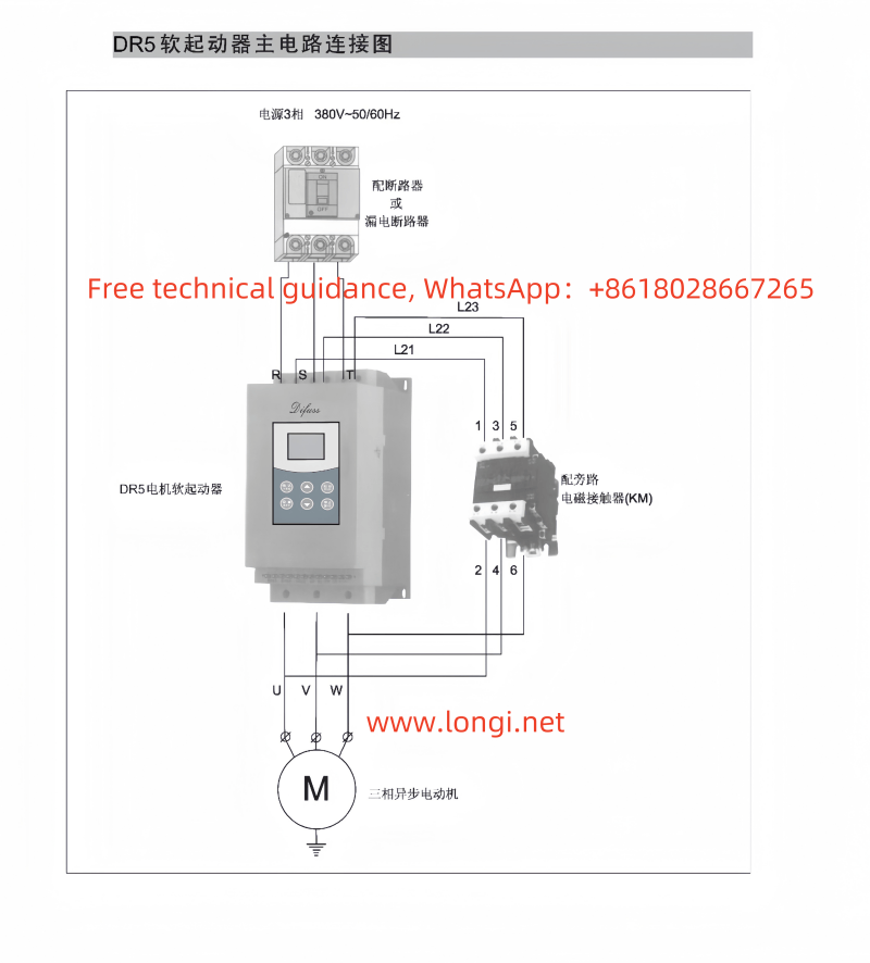
DR5 series Defuss soft start main circuit wiring diagram

I. External Terminal Control Operation Methods

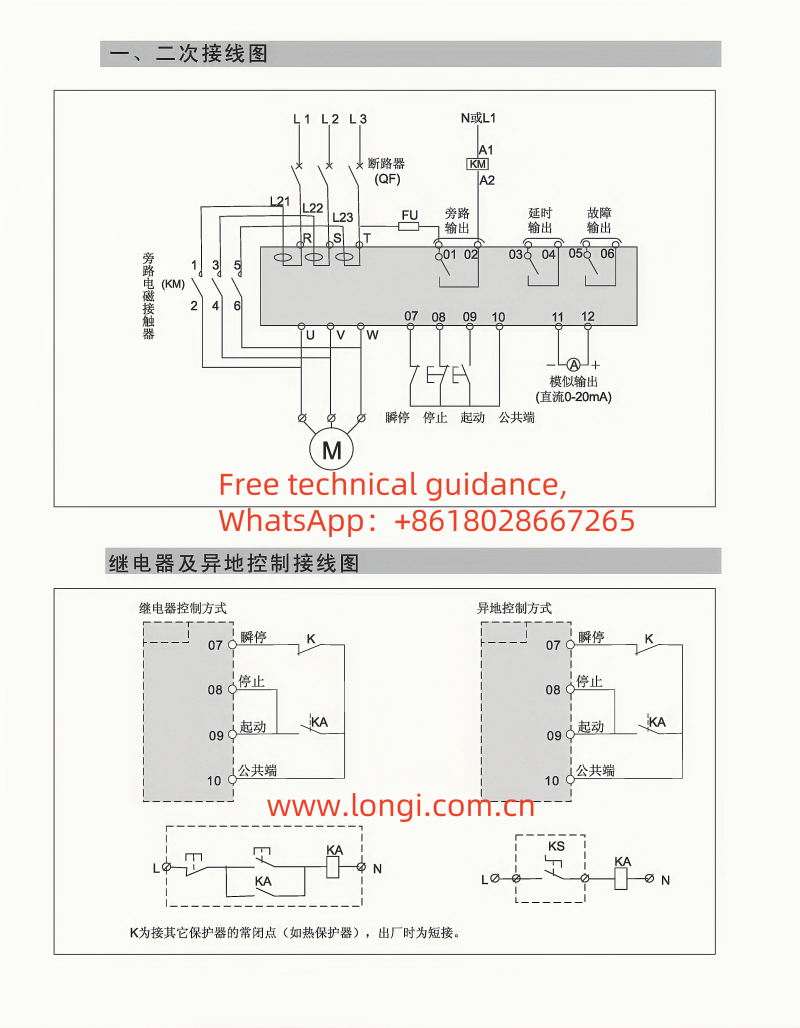
1. External Terminal Configuration

The DR5 Series Soft Starter offers an extensive range of external terminal interfaces for remote control and status feedback. Users should connect external control signals (such as start, stop, reset, etc.) to the corresponding terminals based on their actual needs. Refer to the wiring diagram in the device’s manual for specific terminal configuration.

2. Start Operation

  • Power On: First, ensure that the power supply to the soft starter is correctly connected, and the motor wiring is accurate.
  • External Start Signal: Send a start signal (typically a normally open contact closure) to the start terminal of the soft starter. Subsequently, the soft starter will initiate the predefined start sequence, smoothly initiating motor rotation.

3. Stop Operation

  • External Stop Signal: Transmit a stop signal (also typically a normally open contact closure) to the stop terminal of the soft starter. The soft starter will then gradually reduce the motor’s speed to a stop, following the configured stop mode (e.g., free coasting, soft stop).

4. Reset Operation

  • Fault Reset: When the soft starter stops due to a fault, address the fault source first. Then, send a reset signal (either a pulse signal or a sustained closure signal) to the reset terminal to restore the soft starter to its normal state.

II. Fault Codes and Handling Methods

1. Common Fault Codes

During operation, the DR5 Series Soft Starter may encounter various faults, with corresponding fault codes displayed on its screen. Here are some common fault codes and their possible causes:

  • F01: Overcurrent Fault. It could be caused by excessive motor load or incorrect motor parameter settings.
  • F02: Overload Fault. The motor has been operating in an overloaded state for an extended period.
  • F03: Overheat Fault. The internal temperature of the soft starter is too high, potentially due to poor heat dissipation or a high ambient temperature.
  • F04: Phase Loss Fault. The input power supply or motor is missing one or more phases.
  • F05: Communication Fault. Communication with the host computer or remote control system has been interrupted.

2. Handling Methods

  • Check Power Supply and Motor: Verify that the input power supply is normal, the motor wiring is accurate, and there are no short circuits or open circuits.
  • Adjust Parameters: Adjust the relevant settings of the soft starter, such as startup time and stop mode, according to the actual motor parameters.
  • Improve Heat Dissipation: Clean dust around the soft starter, ensure proper ventilation, and reduce the ambient temperature.
  • Check Communication Lines: Inspect the communication lines with the host computer or remote control system to ensure stable and reliable connections.
  • Restart the Device: After addressing the fault and resetting, attempt to restart the soft starter to observe whether it returns to normal operation.

Conclusion

The Difuss DR5 Series Motor Soft Starter is a powerful and user-friendly motor control device. By correctly configuring the external terminals, mastering operational methods, and promptly handling fault codes, users can fully leverage its performance advantages, achieving smooth motor startup and shutdown while enhancing production efficiency and equipment safety. We hope this article provides valuable guidance for users in utilizing and maintaining the DR5 Series Soft Starter.