Posted on Leave a comment

JACT AT500 Inverter Operation Guide and Fault Handling Summary

AT500 Inverter Operation Guide and Fault Handling Summary


I. AT500 Inverter Operation Panel Usage

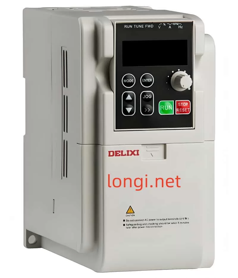
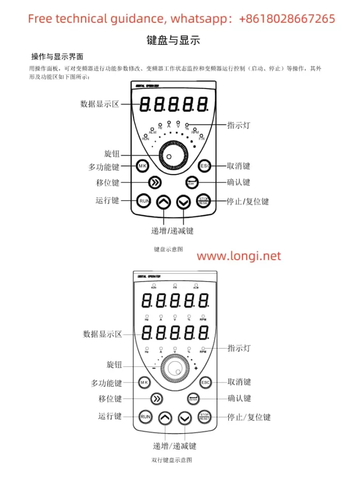
  1. Operation Panel Layout and Indicator Description:
    • Introduces the display, buttons (RUN, STOP/RES, MK, Λ, V, >>, etc.) on the operation panel and their functions.
    • Explains the meanings of various indicators (Run, Alm, Hz, A, V, %, rpm, F/R, etc.).
  2. Menu and Parameter Settings:
    • Describes the three-level menu mode (function parameter group, function code, function code modification) and its operation method.
    • Elaborates on how to view and modify various inverter parameters through the operation panel.
  3. Operation Mode Control:
    • Introduces starting the inverter via the RUN button and stopping it via the STOP/RES button.
    • Explains the jog operation function and its debugging applications.
Function diagram of AT500 inverter operation panel buttons

II. Terminal Control and External Potentiometer Debugging Mode Setup

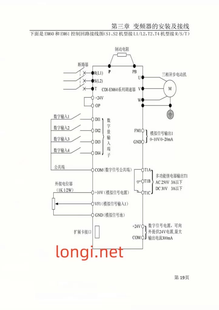
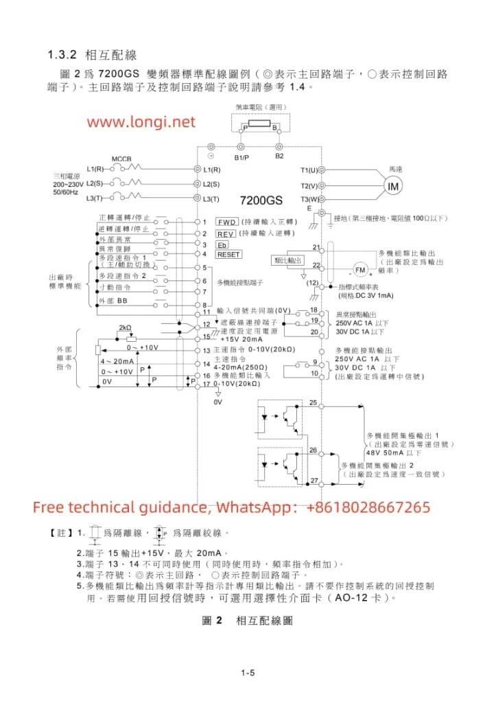
  1. Terminal Control Setup:
    • Guides users to enter the F0 parameter group and set F0.02 to 1 to enable terminal control.
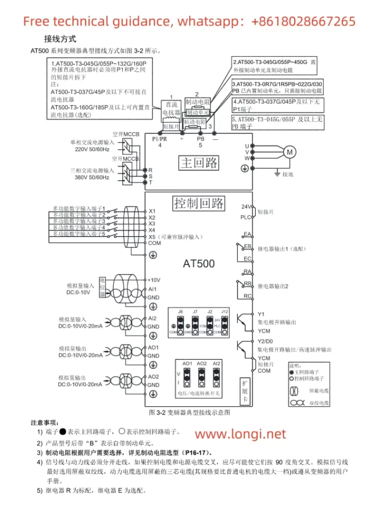
    • Demonstrates how to assign functions to each input terminal through the F2 parameter group and explains wiring requirements.
  2. External Potentiometer Debugging Mode:
    • Teaches users to set F0.03 or F0.04 to AI3 (keyboard potentiometer) to adjust the output frequency by rotating the potentiometer knob.
JACT AT500 inverter wiring diagram

III. Inverter Fault Code Classification and Troubleshooting Methods

  1. Overcurrent Faults (Err02-Err04):
    • Lists possible causes (output circuit short circuit, too short acceleration/deceleration time, etc.).
    • Provides solutions (check output circuit, adjust acceleration/deceleration time, etc.).
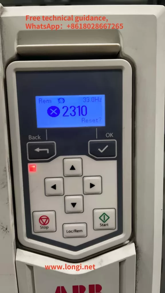
  2. Overvoltage Faults (Err05-Err07):
    • Analyzes fault causes (excessively high input voltage, external force during deceleration, etc.).
    • Offers remedies (adjust input voltage, eliminate external force during deceleration, etc.).
  3. Undervoltage Fault (Err09):
    • Describes fault causes (instantaneous power failure, low input voltage, etc.).
    • Suggests solutions (check input power supply, adjust voltage range, etc.).
  4. Overload Faults (Err10-Err11):
    • Indicates faults may be caused by excessive load, motor stall, etc.
    • Proposes reducing the load, checking the motor and mechanical conditions, etc.
  5. Input/Output Phase Loss Faults (Err12-Err13):
    • Analyzes fault causes (input power phase loss, faulty output wires or motor, etc.).
    • Offers advice on checking power and motor, troubleshooting peripheral faults, etc.
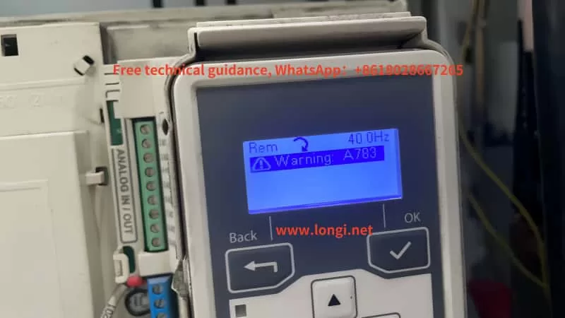
  6. Module Overheating Fault (Err14):
    • Explains fault causes (high ambient temperature, blocked air ducts, etc.).
    • Emphasizes the importance of reducing ambient temperature, cleaning air ducts, replacing fans, etc.
  7. Communication Fault (Err16):
    • Mentions possible causes (incorrect communication parameter settings, faulty communication cables, etc.).
    • Suggests checking communication parameters, cables, and the host computer.
Posted on Leave a comment

Maintenance and Care Guidelines for NETZSCH TG209 Thermogravimetric Analyzer Ensuring Optimal Performance and Longevity

Maintenance and Care for NETZSCH TG209 Thermogravimetric Analyzer: Ensuring Long-Term Stability and Measurement Accuracy

Physical picture of the NIO TG209 thermogravimetric analyzer

Maintaining and caring for the NETZSCH TG209 Thermogravimetric Analyzer is crucial to ensure its long-term stability and measurement accuracy. Here are some key steps and considerations for proper maintenance:

I. Daily Cleaning

  1. Cleaning Sample Pans: Keep sample pans clean before and after each measurement. Use air blowing or appropriate cleaning solutions to clean them, ensuring samples are not damaged.
  2. Cleaning Temperature Controller: Regularly clean the temperature controller with cleaning solutions or air blowing to ensure accurate temperature settings.
  3. Cleaning Computer: Clean the computer’s internal and external components, as well as input/output devices, at least once a year.
Dismantling and Cleaning Diagram of Naichi TG209 Thermogravimetric Analyzer

II. Component Inspection and Replacement

  1. Inspecting Accessories: Regularly inspect the analyzer’s accessories, such as heating elements, controllers, and temperature sensors, to ensure they are in good condition. Replace any aged or damaged components promptly.
  2. Replacing Filters: Based on usage, regularly replace oil absorption filters, filter elements, and gas filters to prevent contaminants from affecting measurement results.
  3. Checking and Replacing Sealing Rings: Regularly inspect the main unit and analyzer for any oil leaks. Replace sealing rings or gaskets if necessary.
Actual calibration diagram of thermogravimetric analyzer

III. Software and System Settings

  1. Software Updates: Keep the analyzer’s control software up to date to utilize the latest features and bug fixes.
  2. System Configuration: Ensure all system settings, such as temperature range and heating rate, are correctly configured to meet experimental requirements.

IV. Regular Maintenance

  1. Professional Maintenance: Request regular maintenance services from NETZSCH or authorized service centers, including deep cleaning, calibration, and performance checks.
  2. Long-Term Storage: If the analyzer will not be used for an extended period, follow the manufacturer’s recommendations for storage and maintenance to prevent component aging and damage.

V. Operational Considerations

  1. Sample Preparation: Ensure samples are uniform powders, and sample pans are dry to reduce measurement errors.
  2. Operational Procedures: Follow the NETZSCH TG209 Thermogravimetric Analyzer’s operating procedures and safety guidelines to ensure operator and equipment safety.
  3. Maintenance Logs: Establish a maintenance log to record the time, content, and replaced components of each maintenance activity, allowing for tracking of the equipment’s maintenance history and performance changes.

VI. Specific Maintenance Tasks

  1. Cleaning Support Rods: After prolonged use, support rods may accumulate residue from sample decomposition, affecting test accuracy. Regularly burn support rods in air or oxygen atmospheres at high temperatures to remove residue (typically once a week, depending on sampling frequency and instrument contamination).
  2. Furnace Maintenance: For models like the NETZSCH TG209F1 with ceramic furnaces, pay special attention to the furnace’s corrosion resistance and sealing. Regularly inspect the furnace for cracks or damage and repair promptly.

By considering these aspects of daily cleaning, component inspection and replacement, software and system settings, regular maintenance, operational considerations, and specific maintenance tasks, you can ensure the long-term stability and measurement accuracy of your NETZSCH TG209 Thermogravimetric Analyzer.

Posted on Leave a comment

Reasons for Slow Speed of Centrifuge Inverter and Solutions

Centrifuge frequency converter control cabinet

Centrifuges, as commonly used separation equipment in laboratories and industrial fields, rely heavily on stable and efficient rotational speed for optimal separation results and productivity. However, in practical applications, users may encounter issues where the centrifuge inverter operates at a sluggish pace, which not only affects separation effectiveness but also increases the risk of equipment failures. This article will analyze the reasons behind the slow speed of centrifuge inverters from multiple perspectives and provide corresponding solutions.

I. Reasons for Slow Speed of Centrifuge Inverter

  1. Excessive Material Load
    When the amount of material being processed by the centrifuge exceeds its design capacity, the rotational speed naturally suffers, leading to sluggish acceleration. In such cases, reducing the material load is necessary to avoid overloading the centrifuge.
  2. Accumulation of Impurities Inside the Centrifuge
    The interior of a centrifuge is prone to accumulating dust and other impurities, which can increase the rotational resistance of the rotor, thereby affecting the speed. Regular cleaning of the centrifuge to maintain equipment cleanliness is crucial to addressing this issue.
  3. Damage to Rotor Bearings
    Damage to rotor bearings can not only cause a decrease in rotational speed but also lead to abnormal noises. Inspecting and replacing damaged rotor bearings can restore the centrifuge to its normal operating speed.
  4. Loose or Worn Drive Belts
    Loose or worn drive belts are common causes of slow centrifuge speed. Regular inspection of belt tension and wear, along with timely replacement of damaged components, can ensure the proper functioning of the centrifuge.
  5. Motor Failures
    Motor failures, such as winding circuit breaks, rotor fractures, or inverter malfunctions, directly impact the rotational speed of the centrifuge. In such situations, motor replacement or electrical circuit repairs are necessary.
  6. Improper Inverter Parameter Settings
    As the key device controlling the centrifuge’s rotational speed, improper settings of the inverter parameters can also lead to sluggish speed. Checking and adjusting the inverter parameters to match the actual requirements of the centrifuge is essential.
  7. Electrical Control System Malfunctions
    Issues with components in the electrical control system, such as adjustable resistors, thyristors, and rectifier diodes, can also cause unstable motor speed. Regular inspection of these components and timely replacement of damaged parts are important measures for maintaining the stability of the centrifuge’s electrical control system.
Centrifuge and control system

II. Solutions

  1. Adjust Material Load
    Reasonably adjust the material load based on the centrifuge’s processing capacity to avoid overload operation.
  2. Regularly Clean the Centrifuge
    Establish a regular cleaning schedule to ensure the centrifuge is free from impurity accumulation and remains clean.
  3. Inspect and Replace Damaged Components
    Regularly inspect the condition of key components such as rotor bearings and drive belts, and promptly replace any damaged parts.
  4. Adjust Inverter Parameters
    Adjust the inverter parameters according to the actual needs of the centrifuge to ensure stable rotational speed and compliance with process requirements.
  5. Enhance Electrical Control System Maintenance
    Regularly inspect the condition of components in the electrical control system, such as adjustable resistors, thyristors, and rectifier diodes, and promptly repair or replace any damaged parts.
  6. Professional Repair and Technical Support
    For complex fault issues, seek the assistance of professional repair personnel and technical support to ensure the centrifuge receives proper maintenance and repair.

III. Conclusion

The slow speed of a centrifuge inverter can be attributed to various factors, including excessive material load, accumulation of impurities inside the centrifuge, damage to rotor bearings, loose or worn drive belts, motor failures, improper inverter parameter settings, and electrical control system malfunctions. By implementing measures such as adjusting material load, regularly cleaning the equipment, promptly replacing damaged components, adjusting inverter parameters, and enhancing electrical control system maintenance, the issue of slow centrifuge inverter speed can be effectively resolved, thereby improving the operational efficiency and stability of the equipment. Additionally, for complex fault issues, seeking professional repair and technical support is essential.

Posted on Leave a comment

External Terminal Start & Potentiometer Speed Control with Password Security and Fault Code Analysis on CDI-EM60 and EM61 Series Inverters from Hangzhou Delixi

The CDI-EM60 and EM61 series variable frequency drives (VFDs) from Hangzhou Delixi boast robust functionalities in industrial control applications. This article delves into the external terminal start and external potentiometer speed control features of these inverters, alongside an overview of their password security and fault code analysis capabilities.

I. External Terminal Start


Pictures of Hangzhou Delixi CDI-EM60 and EM61 series drivers

The CDI-EM60 and EM61 series VFDs support versatile starting methods, including keypad control, terminal control, and communication control. External terminal start is a popular and flexible method, triggering the inverter’s start and stop through external signals.

Setup Steps for External Terminal Start:

  1. Parameter Configuration:
    • Set the P0.0.03 (Operation Control Mode Selection) to 1 for terminal control.
    • Adjust other relevant parameters such as acceleration/deceleration times and frequency sources as needed.
  2. Wiring:
    • Connect external control signals to the corresponding input terminals of the inverter (e.g., DI1, DI2).
    • Ensure compatibility between the external signal source (e.g., pushbuttons, relay contacts) and the inverter input terminals.
  3. Testing:
    • Power on and test if the external control signals correctly trigger the inverter’s start and stop.
    • Fine-tune parameters for a smooth start-up process.

Precautions:

  • Ensure external control signals adhere to the inverter’s electrical specifications.
  • Regularly inspect wiring for secure connections to prevent control failures.
Delixi VFD CDI-EM60 and EM61 External Terminal Control Wiring Diagram

II. External Potentiometer Speed Control

External potentiometer speed control adjusts the inverter’s output frequency by rotating an external potentiometer, thereby regulating motor speed.

Setup Steps for External Potentiometer Speed Control:

  1. Parameter Configuration:
    • Set the P0.0.04 (Frequency Source Selection) to 2 (Keypad Potentiometer) or 1 (External Terminal VF1, if connecting the potentiometer to VF1).
    • Adjust parameters like maximum frequency and acceleration time to suit speed control requirements.
  2. Wiring:
    • Connect the wiper, fixed terminal, and variable terminal of the potentiometer to the corresponding inverter terminals (e.g., VF1, GND).
    • Ensure the potentiometer’s electrical specifications match the inverter’s input requirements.
  3. Testing:
    • Rotate the potentiometer and observe if the inverter’s output frequency varies accordingly.
    • Adjust the potentiometer’s rotation range and inverter parameters for optimal speed control.

Precautions:

  • Regularly check potentiometer connections for reliability to prevent speed instability.
  • Avoid sudden disconnection or short-circuiting of potentiometer wiring during inverter operation.

III. Password Settings and Decoding

The Delixi inverters offer password protection to restrict unauthorized parameter modifications.

Password Setup:

  1. Access the Password Menu:
    • Navigate through the inverter’s keypad to the parameter setting interface.
    • Locate the password-related function code (e.g., P5.0.20) and enter the password setup menu.
  2. Enter the Password:
    • Input a custom 5-digit password.
    • Confirm the password and save changes before exiting the setup menu.

Password Decoding and Recovery:

  • Decoding: Enter the correct password to lift password protection and regain full inverter control.
  • Password Recovery: If forgotten, contact the inverter supplier or manufacturer for unlocking or password reset.

IV. Fault Code Analysis

During operation, the Delixi inverters may display fault codes indicating the device’s status and fault types.

  • Err01: Overcurrent During Constant Speed. Possible causes include output circuit shorts or load surges. Inspect and resolve issues before restarting the inverter.
  • Err02: Overcurrent During Acceleration. Might stem from motor/circuit shorts or inadequate acceleration time. Adjust parameters or check wiring.
  • Err04: Overvoltage During Constant Speed. Verify input voltage and bus voltage readings.
  • Err07: Module Fault. Could indicate inverter module damage, requiring replacement or professional service.
  • Err10: Motor Overload. Check for motor blockage or excessive loads, adjust motor protection parameters, or reduce the load.

Consulting the inverter manual’s fault code table enables swift troubleshooting and ensures uninterrupted production.

In conclusion, the CDI-EM60 and EM61 series VFDs from Hangzhou Delixi excel in industrial control with their versatile starting mechanisms, precise speed regulation, robust security features, and intuitive fault diagnosis. Mastering these functionalities optimizes device performance and enhances operational safety.

Posted on Leave a comment

Operation Guide and Fault Code Analysis of TECO Inverter 7200GS

The TECO Inverter 7200GS, as a high-performance universal inverter, is widely used in industrial automation due to its support for various control modes including V/F control, Sensorless Vector Control, PID energy-saving control, and V/F+PG closed-loop control. This article will provide a detailed introduction to key operations of the TECO Inverter 7200GS, including panel startup, frequency speed regulation, password function setup and unlocking, as well as fault code analysis.

TECO inverter image

I. Panel Startup

1. Inspection and Preparation

  • Verify the Inverter Installation Environment: Check if the surrounding temperature, humidity, and ventilation conditions meet the requirements, ensuring no corrosive gases or dust.
  • Electrical Inspection: Ensure all electrical connections, particularly the input/output power supply and motor connections, are correct.

2. Power-On Startup

  • Connect the main power supply to the inverter. The “CHARGE” indicator light will illuminate, indicating that the internal capacitor is charging.
  • Once the “CHARGE” indicator light goes out, it means charging is complete, and the inverter is ready for operation.

3. Panel Operation

  • Use the standard LCD or LED operator panel to switch to the “DRIVE” mode.
  • Press the “RUN” button to start the inverter, and the motor will subsequently operate.

II. Panel-Set Frequency Speed Regulation

1. Enter Frequency Setting Mode

  • In the “DRIVE” mode, navigate to the frequency setting interface using the number keys and direction keys on the panel.
  • Use the direction keys to select the “Frequency Command” option and input the desired frequency value using the number keys.

2. Speed Regulation Operation

  • After entering the frequency value, press the “ENTER” key to confirm, and the inverter will adjust the motor speed according to the set frequency value.
  • Smooth speed regulation can be achieved by continuously changing the frequency value.

III. Password Function Setup and Unlocking

1. Password Setup

  • With the inverter stopped, enter the parameter setting mode through the panel.
  • Locate the parameter related to password setup (e.g., Sn-xx) and input the desired password value according to your needs.
  • Save the parameter settings and exit the setup mode after completing the password setup.

2. Password Unlocking

  • To unlock a set password protection, re-enter the parameter setting mode.
  • Input the correct password value, save, and exit the setup mode to remove the password protection.

IV. Fault Code Analysis

1. UV1 (Under Voltage)

  • Fault Description: The DC main circuit voltage is too low during operation.
  • Possible Causes: Insufficient power supply capacity, voltage drop in wiring, improper inverter power supply voltage selection, etc.
  • Countermeasures: Check the power supply voltage and wiring, verify the power supply capacity and system, install an AC reactor, etc.

2. OC (Over Current)

  • Fault Description: The inverter output current exceeds 200% of the rated current.
  • Possible Causes: Short acceleration time, short circuit or grounding at the output terminals, motor capacity exceeding the inverter capacity, etc.
  • Countermeasures: Extend the acceleration time, check the output terminal wiring, replace the inverter with an appropriate capacity, etc.

3. OL3 (Over Load)

  • Fault Description: Excessive output torque triggers the over-torque protection.
  • Possible Causes: Abnormal mechanical load, improper over-torque detection level settings, etc.
  • Countermeasures: Inspect the mechanical operation, set an appropriate over-torque detection level, etc.

4. PG0 (PG Disconnection)

  • Fault Description: Disconnection of the PG (encoder) signal.
  • Possible Causes: Poor contact or disconnection in the PG wiring.
  • Countermeasures: Check the PG wiring to ensure proper contact.

V. Conclusion

The TECO Inverter 7200GS, as a powerful inverter, offers flexible speed regulation, startup, and protection functions. Through this article, users can better understand and master key operations such as panel startup, frequency speed regulation, password settings, and fault code analysis, thereby enhancing equipment efficiency and stability. In practical applications, users should configure inverter parameters according to specific needs and environmental conditions to ensure proper operation.

Posted on Leave a comment

ABB Inverter ACS530 Series Alarm 2310: Causes and Solutions

The ACS530 series inverter from ABB, a leading player in industrial automation, is widely utilized across various industries. However, during operation, users may encounter various fault alarms, with alarm code 2310 being a common one, indicating an overcurrent fault. Based on the provided documentation, this article delves into the causes and corresponding solutions for ABB Inverter ACS530 series alarm 2310.

I. Causes of Alarm 2310

1. Excessive Motor Load

When the motor load exceeds its rated capacity, it can lead to a sharp increase in current, triggering the overcurrent protection. This may be due to an overly heavy load driven by the motor, mechanical jams, or motor stalls.

2. Incorrect Inverter Parameter Settings

The parameter settings of the inverter significantly impact its operational performance. Improper settings for acceleration time, deceleration time, or low current limits and overload protections can cause excessive current during motor startup or operation, resulting in an overcurrent alarm.

3. Unstable Power Supply Voltage

Fluctuations in power supply voltage directly affect the output voltage and current of the inverter. Unstable power supply can prevent the inverter from operating steadily, causing the output current to exceed normal ranges and trigger the overcurrent protection.

4. Motor or Cable Faults

Internal motor shorts, open windings, or grounding faults in motor cables can lead to excessive current. Additionally, contactors in the motor cable that are opening or closing can generate instantaneous high currents during switching, causing an overcurrent alarm.

5. Internal Inverter Faults

Damage or aging of internal components such as power modules, drive circuits, or current detection circuits in the inverter can result in unstable output currents, triggering an overcurrent alarm.

II. Solutions

1. Check Motor Load

First, inspect if the motor’s driven load is excessive. If so, attempt to reduce the load or replace the motor and inverter combination with higher capacities. Additionally, check for mechanical jams or stalls and address them promptly.

2. Review and Adjust Inverter Parameters

Examine the inverter’s parameter settings, particularly acceleration time, deceleration time, current limits, and overload protections. Ensure these settings are appropriate for the motor’s actual operational requirements. Adjust them if found to be incorrect.

3. Stabilize Power Supply Voltage

Use a multimeter or similar tools to check the stability of the power supply voltage. If significant fluctuations are present, implement measures to stabilize it, such as installing voltage stabilizers or UPS systems.

4. Inspect Motor and Cables

Examine the motor and motor cables for faults. Check for short circuits or open windings in the motor, verify the insulation resistance of the cables, and ensure no power factor correction capacitors or surge absorbers are present in the cables that could contribute to abnormal currents.

5. Check Internal Inverter Components

If all the above checks are normal, the overcurrent alarm may be due to internal inverter component damage. Contact professional technicians for inspection or replacement of faulty internal components.

III. Preventive Measures

To avoid the occurrence of ABB Inverter ACS530 series alarm 2310, adopt the following preventive measures:

Regular Inspections and Maintenance: Conduct periodic inspections and maintenance of the motor and inverter to ensure their smooth operation.

Appropriate Parameter Settings: When setting inverter parameters, base them on the motor’s actual conditions to prevent incorrect settings from causing overcurrent faults.

Stable Power Supply Voltage: Maintain stable power supply voltage to prevent its fluctuations from affecting the inverter’s performance.

Suitable Motor and Inverter Selection: Choose motors and inverters that match the actual load requirements to prevent overcurrent faults due to excessive loads.

In conclusion, ABB Inverter ACS530 series alarm 2310 is a critical fault alarm that requires attention. By thoroughly examining motor loads, adjusting inverter parameters, stabilizing power supply voltage, inspecting motors and cables, and checking internal inverter components, this issue can be effectively resolved, ensuring the inverter’s smooth operation. Furthermore, implementing preventive measures can reduce the likelihood of overcurrent faults and enhance the reliability and stability of the equipment.