
When repairing Mitsubishi servo drives, encountering damaged modules is common. After repairing such modules, it’s crucial to test the drive board’s output function offline before reinstallation. This article provides a detailed guide for testing a repaired Mitsubishi MR-J3-350A/3.5KW servo module.
Preparation for Offline Testing:
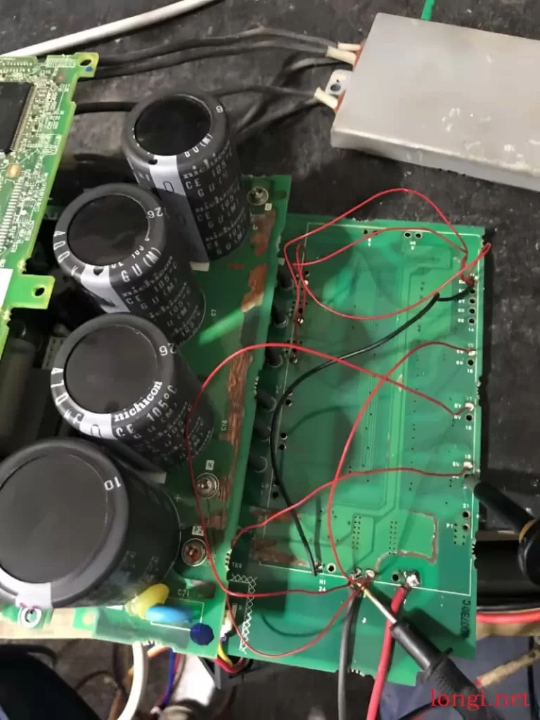
- Power Connection: Connect 300V DC voltage to power boards P2 and N to avoid E9 fault after power-on.
- Module Pad Hole Shielding:
- Connect the 10 pins of the module pad hole to N.
- Connect pad holes U, V, W to N to prevent AL24 fault.
- Connect pad holes EV, EU, EW (upper axle drive trigger) to N.
Parameter Setting Before Running:
- Change PA01: Set PA01 to 0002.
- Change PD01: Set PD01 to 0000.
- Power Board Connection: Connect P and D on the power board.
- Additional Power Board Connections: Connect L1 to L11 and L2 to L12 on the power board.
- If PD parameters are not visible, change PA19 to 000C and power on again.
Testing Process:
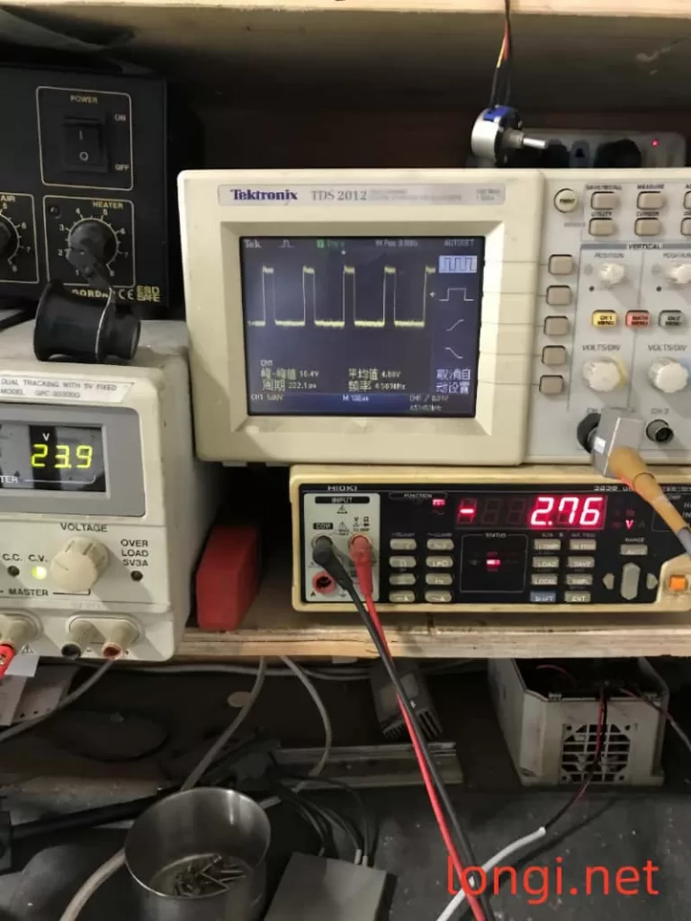
- After following the above steps, power on and run the servo to test its 6-way waveform.
- During parameter waveform testing, manually rotate the motor shaft to observe changes in pulse width and phase in the waveform. Note that this machine does not have a static cut-off negative voltage.
By following this comprehensive guide, you can effectively test the offline operation of a repaired Mitsubishi MR-J3 servo driver maintenance board, ensuring its functionality before reinstallation.