
Repair an imported Siemens 7.5kW frequency converter due to power supply hiccup fault, with no display on the operation panel. Due to its special installation structure, the machine is surrounded by three circuit boards and a heat dissipation plate in a square shape, with an embedded shell. When repairing, it is necessary to disconnect the circuit board and lay the entire circuit flat on the workbench, such as unfolding a roll of ancient bamboo slips, in order to facilitate maintenance. Moreover, the circuit board is a four layer board, making circuit maintenance difficult.
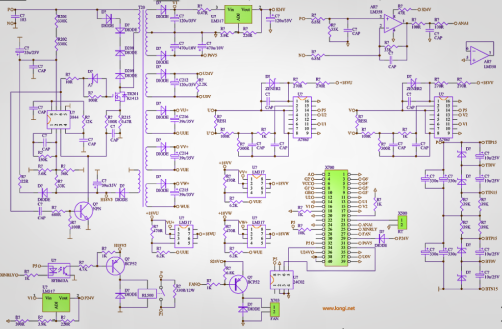
Starting from the switch power supply circuit, first use the elimination method to cut off the load circuit one by one. If it still cannot vibrate well, it indicates that hiccups are not caused by excessive load. There are no abnormalities in the oscillation and voltage stabilization circuits. Finally, it was found that two 200V voltage stabilizing tubes in the cut-off shunt circuit of the switch tube were damaged due to breakdown. We purchased 110V voltage stabilizing tubes from the market and replaced them with four to repair them. A typical shunt (also known as anti peak voltage absorption) circuit uses a diode connected in series with a resistance capacitance parallel circuit, and then connected in parallel with the primary winding of a switching transformer. The diode connection method is similar to the freewheeling diode connection method of a typical coil circuit. Its function is to quickly release the electrical energy of the primary winding circuit during the period when the switching transistor is approaching cutoff, so that the switching transistor can cut off more quickly. But the circuit consists of two 200V voltage regulators connected in series from the P+end, followed by two thermistors with resistance values of 360k each, connected in series to the drain of the switching tube. The circuit is also connected in parallel to the primary winding. When the switch tube tends to cut off, the sharp decrease in current in the primary winding causes a sharp increase in the back electromotive force of the winding. When it is superimposed with the power supply voltage and exceeds the P+voltage by 400V, this protective circuit breaks down and conducts, releasing this energy back to the power supply. When the back electromotive force energy is small, the current flowing through the two thermistors is small, their temperature rise is also small, their resistance value is large, and the release of energy is also slow. When the back electromotive force energy is large, as the discharge current increases, the resistance temperature rises, the resistance value decreases, and the energy discharge is accelerated. Think about it, this circuit is connected in series with a thermistor, it’s really interesting. Adding a thermistor and a peak voltage absorption circuit with voltage stabilizing diodes to the primary winding of the switch transformer may only be done by Siemens frequency converters. I have also encountered this type of circuit form for the first time.