The ABB ACS800 VFD (Variable Frequency Drive) plays a pivotal role in industrial automation, finding extensive applications across various industrial control systems. However, during operation, it may encounter various alarm messages.
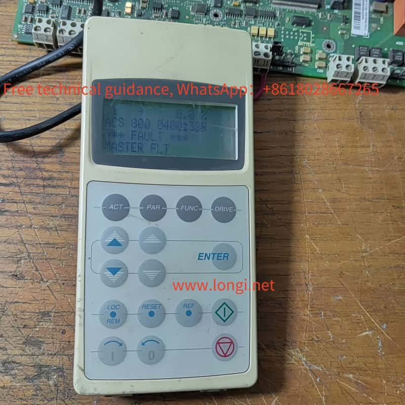
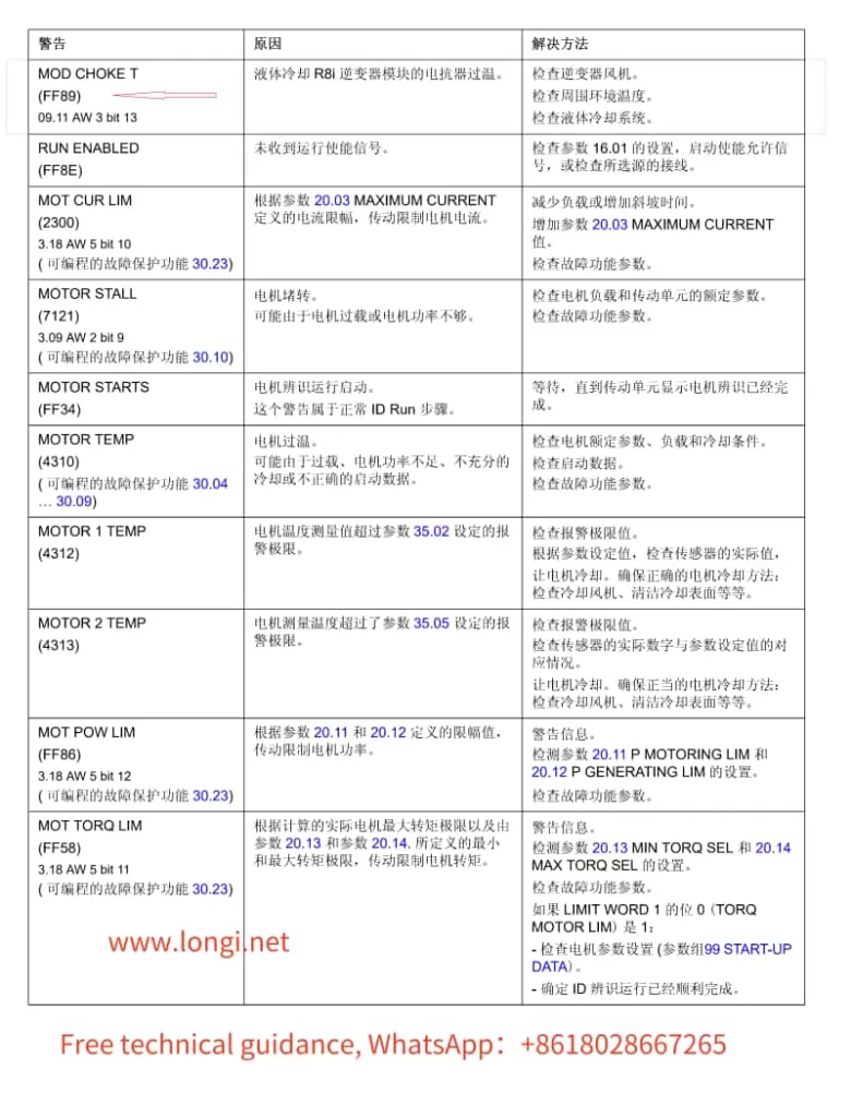
Alarm Message: FF89 – MOD CHOKE T (FF89) 09.11 AW 3 bit 13
Cause:
Overheating of Reactor in Liquid-Cooled R8i Inverter Module The reactor in the liquid-cooled R8i inverter module has exceeded its temperature threshold.
Resolution Steps:
Check the Inverter Fan:
Ensure the inverter fan is operating properly and providing sufficient cooling to the reactor.
Inspect for any blockages or dirt accumulation that may impede airflow.
Inspect Ambient Temperature:
Verify that the ambient temperature surrounding the VFD is within the recommended range.
Ensure there are no heat sources in close proximity that could contribute to overheating.
Examine the Liquid Cooling System:
Thoroughly check the condition of the liquid cooling system, including pipes, pumps, and radiators.
Confirm that the coolant flow rate and temperature are within normal operating parameters.
Inspect for leaks or corrosion that could indicate a need for maintenance or replacement.
Review VFD Operation and Configuration:
Ensure the VFD is not operating under excessive load conditions that could lead to overheating.
Check the VFD’s settings and parameters to verify they are appropriate for the application and load requirements.
Check for Alarms or Warnings in the VFD’s Diagnostic System:
Use the VFD’s diagnostic tools or software (such as DriveWindow) to check for any additional alarms or warnings that may provide further insight into the issue.
Service and Maintenance:
If the above steps do not resolve the issue, consider scheduling preventive maintenance or contacting ABB support for further assistance.
By following these resolution steps, you can effectively diagnose and address the FF89 alarm on your ABB ACS800 VFD, ensuring reliable and efficient operation of your industrial automation system.
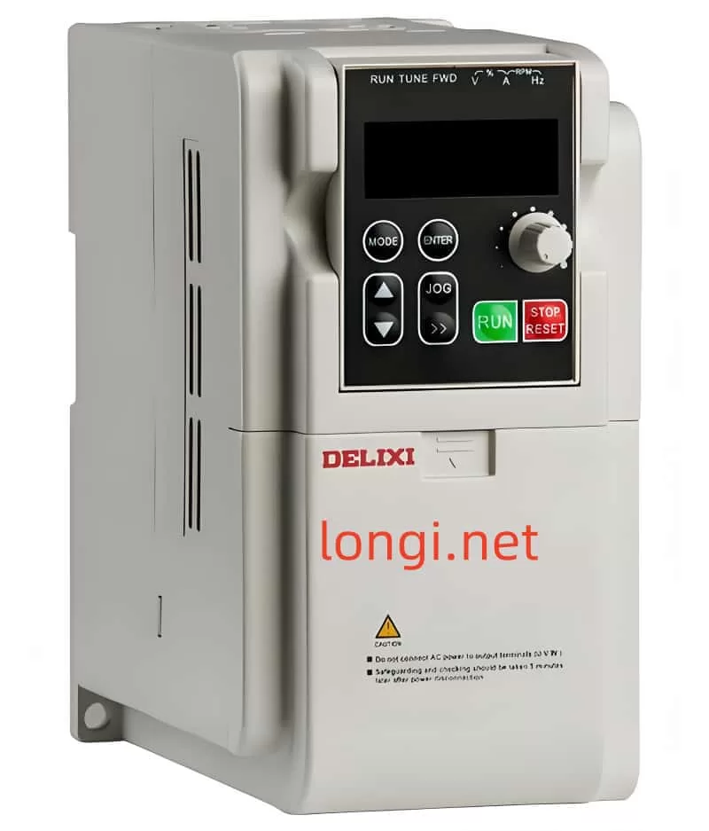
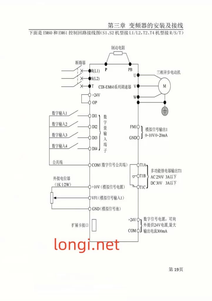
The CDI-EM60 and EM61 series variable frequency drives (VFDs) from Hangzhou Delixi boast robust functionalities in industrial control applications. This article delves into the external terminal start and external potentiometer speed control features of these inverters, alongside an overview of their password security and fault code analysis capabilities.
I. External Terminal Start
The CDI-EM60 and EM61 series VFDs support versatile starting methods, including keypad control, terminal control, and communication control. External terminal start is a popular and flexible method, triggering the inverter’s start and stop through external signals.
Setup Steps for External Terminal Start:
Parameter Configuration:
Set the P0.0.03 (Operation Control Mode Selection) to 1 for terminal control.
Adjust other relevant parameters such as acceleration/deceleration times and frequency sources as needed.
Wiring:
Connect external control signals to the corresponding input terminals of the inverter (e.g., DI1, DI2).
Ensure compatibility between the external signal source (e.g., pushbuttons, relay contacts) and the inverter input terminals.
Testing:
Power on and test if the external control signals correctly trigger the inverter’s start and stop.
Fine-tune parameters for a smooth start-up process.
Precautions:
Ensure external control signals adhere to the inverter’s electrical specifications.
Regularly inspect wiring for secure connections to prevent control failures.
II. External Potentiometer Speed Control
External potentiometer speed control adjusts the inverter’s output frequency by rotating an external potentiometer, thereby regulating motor speed.
Setup Steps for External Potentiometer Speed Control:
Parameter Configuration:
Set the P0.0.04 (Frequency Source Selection) to 2 (Keypad Potentiometer) or 1 (External Terminal VF1, if connecting the potentiometer to VF1).
Adjust parameters like maximum frequency and acceleration time to suit speed control requirements.
Wiring:
Connect the wiper, fixed terminal, and variable terminal of the potentiometer to the corresponding inverter terminals (e.g., VF1, GND).
Ensure the potentiometer’s electrical specifications match the inverter’s input requirements.
Testing:
Rotate the potentiometer and observe if the inverter’s output frequency varies accordingly.
Adjust the potentiometer’s rotation range and inverter parameters for optimal speed control.
Precautions:
Regularly check potentiometer connections for reliability to prevent speed instability.
Avoid sudden disconnection or short-circuiting of potentiometer wiring during inverter operation.
III. Password Settings and Decoding
The Delixi inverters offer password protection to restrict unauthorized parameter modifications.
Password Setup:
Access the Password Menu:
Navigate through the inverter’s keypad to the parameter setting interface.
Locate the password-related function code (e.g., P5.0.20) and enter the password setup menu.
Enter the Password:
Input a custom 5-digit password.
Confirm the password and save changes before exiting the setup menu.
Password Decoding and Recovery:
Decoding: Enter the correct password to lift password protection and regain full inverter control.
Password Recovery: If forgotten, contact the inverter supplier or manufacturer for unlocking or password reset.
IV. Fault Code Analysis
During operation, the Delixi inverters may display fault codes indicating the device’s status and fault types.
Err01: Overcurrent During Constant Speed. Possible causes include output circuit shorts or load surges. Inspect and resolve issues before restarting the inverter.
Err02: Overcurrent During Acceleration. Might stem from motor/circuit shorts or inadequate acceleration time. Adjust parameters or check wiring.
Err04: Overvoltage During Constant Speed. Verify input voltage and bus voltage readings.
Err07: Module Fault. Could indicate inverter module damage, requiring replacement or professional service.
Err10: Motor Overload. Check for motor blockage or excessive loads, adjust motor protection parameters, or reduce the load.
Consulting the inverter manual’s fault code table enables swift troubleshooting and ensures uninterrupted production.
In conclusion, the CDI-EM60 and EM61 series VFDs from Hangzhou Delixi excel in industrial control with their versatile starting mechanisms, precise speed regulation, robust security features, and intuitive fault diagnosis. Mastering these functionalities optimizes device performance and enhances operational safety.