
I. Introduction to Operation Panel Functions
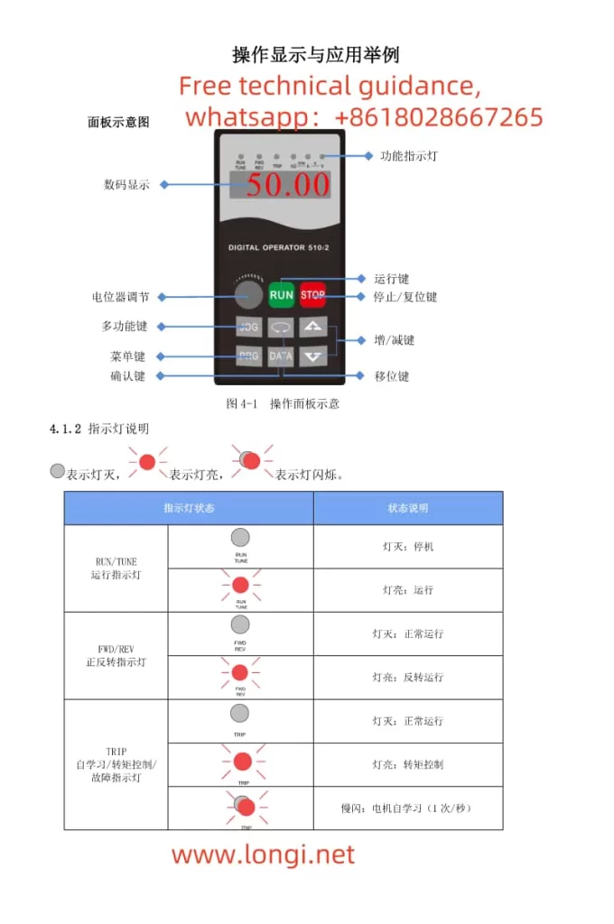
- Panel Diagram and Indicator Descriptions
Panel Diagram: The VFD operation panel typically includes a display screen, confirm button, stop/reset button, potentiometer adjustment, multifunction button, menu button, function indicators, run button, increase/decrease buttons, and shift button.
Indicator Status:
RUN/TUNE: Light off indicates stop, light on indicates operation.
FWD/REV: Light off indicates normal operation, light on indicates reverse operation.
TRIP: Light off indicates normal operation, slow flashing indicates motor self-learning (1 time/second), fast flashing indicates fault (4 times/second). - Setting to Display Actual Speed Instead of Frequency
To display actual speed instead of frequency, the monitoring parameter needs to be adjusted.
Enter the parameter setting interface through the operation panel, locate the d0-19 feedback speed (Hz) function code, and set its value to the relevant parameter for displaying actual speed. The specific parameter value may vary depending on the VFD model and settings. Please refer to the function parameter table and monitoring parameter summary in the manual. - Start, Stop, and Parameter Adjustment Button Operations
Start: Press the run button (RUN) to start the VFD.
Stop: Press the stop/reset button (STOP/RESET) to stop the VFD operation. In fault state, this button can also be used for reset.
Adjust Parameters:
Press the menu button (MENU) to enter the parameter setting menu.
Use the increase/decrease buttons and shift button to select the parameter to be adjusted.
Press the confirm button to enter the parameter modification state, then use the increase/decrease buttons and shift button again to adjust the parameter value.
After adjustment, press the confirm button to save the settings and exit.
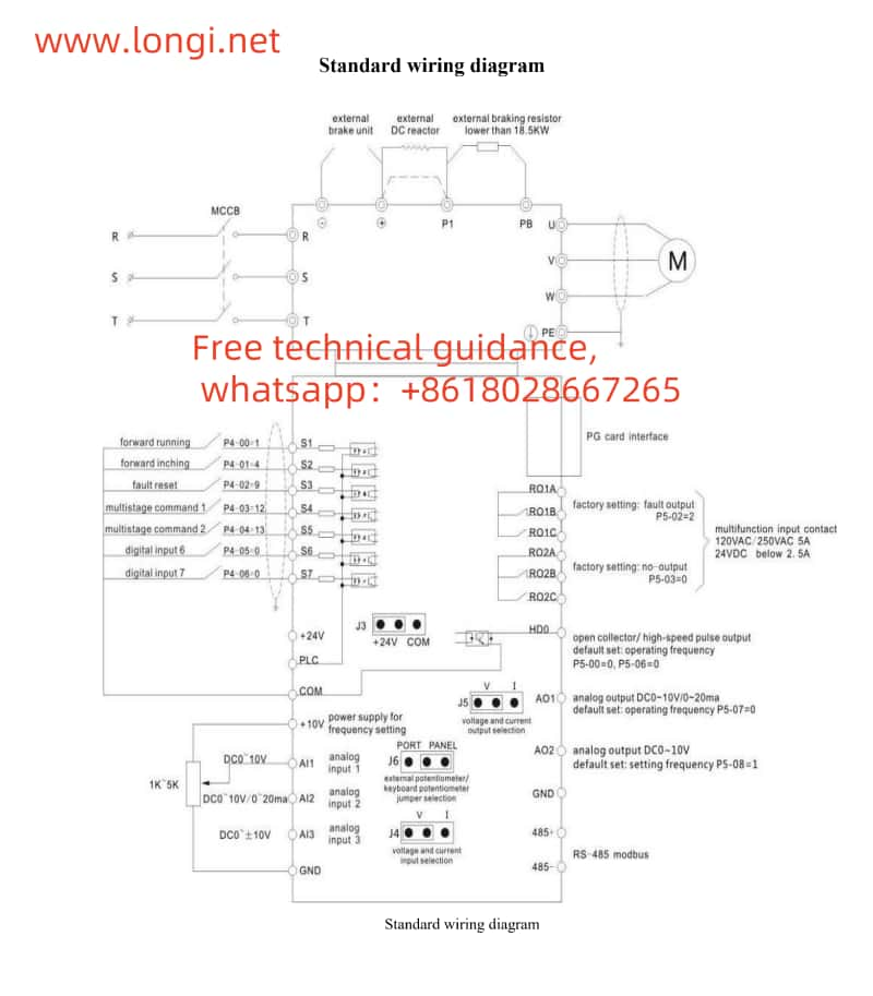
II. Terminal Start and Potentiometer Speed Adjustment Wiring and Parameter Settings
- Terminal Start Wiring
Control Terminals: Typically, digital input terminals such as S1 (forward operation) and S2 (reverse operation) are used for start control.
Wiring Method: Connect external control signals (such as buttons, relay contacts, etc.) to S1 and the common terminal COM for forward start; connect to S2 and the common terminal COM for reverse start. - Potentiometer Speed Adjustment Wiring
Control Terminals: Use analog input terminals such as AI1 and AI2 for potentiometer speed adjustment.
Wiring Method: Connect the sliding end of the potentiometer to the analog input terminal (such as AI1), and connect the fixed ends to +10V and GND (common ground) respectively. - Parameter Settings
Start Parameters:
Set P0-02 operation command channel to 1 (terminal command channel).
According to the wiring, set P4-00 S1 terminal function selection to 1 (forward operation), and P4-01 S2 terminal function selection to 2 (reverse operation).
Speed Adjustment Parameters:
Set P0-03 main frequency source A command selection to 2 (AI1), indicating that AI1 terminal is used for frequency setting.
According to the potentiometer wiring and speed adjustment requirements, set parameters such as P4-13 AI curve 1 minimum input, P4-15 AI curve 1 maximum input, P4-14 AI curve 1 minimum input corresponding setting, and P4-16 AI curve 1 maximum input corresponding setting to define the correspondence between potentiometer output voltage and frequency.
III. VFD Fault Analysis and Solution
- Common Faults and Causes
Overcurrent Fault: May be caused by motor stalling, overload, improper parameter settings, etc.
Overvoltage Fault: May be caused by excessive input voltage, short deceleration time, damaged braking resistor, etc.
Undervoltage Fault: May be caused by insufficient input voltage, power supply failure, etc.
Overheating Fault: May be caused by high ambient temperature, poor VFD heat dissipation, excessive load, etc. - Solutions
Overcurrent Fault: Check if the motor is stalled or overloaded, adjust the load or increase the VFD capacity; check if the parameter settings are reasonable, such as acceleration time, deceleration time, etc.
Overvoltage Fault: Check if the input voltage is normal, adjust the deceleration time or add a braking resistor; check if the braking resistor is damaged or poorly wired.
Undervoltage Fault: Check if the input power supply is normal, and ensure that the power supply voltage is within the allowable range.
Overheating Fault: Improve the VFD heat dissipation conditions, such as increasing ventilation, cleaning dust, etc.; reduce the load or increase the VFD capacity; check if the parameter settings are reasonable, such as carrier frequency, etc. - Fault Troubleshooting Steps
Observe Indicators: Initially judge the fault type based on the indicator status.
View Fault Records: Enter the VFD fault record interface to view the type and occurrence time of the most recent fault or faults.
Check External Wiring: Ensure that all external wiring is correct and free from looseness or short circuits.
Adjust Parameter Settings: According to the fault type and cause, appropriately adjust the VFD parameter settings.
Contact After-sales Service: If the fault cannot be resolved independently, contact the VFD manufacturer or professional maintenance personnel for repair.
Through the above steps, users can effectively use the Oulu EV510 VFD, including operation panel functions, terminal start and potentiometer speed adjustment wiring and parameter settings, as well as fault analysis and solutions.