Posted on Leave a comment

JACT AT500 Inverter Operation Guide and Fault Handling Summary

AT500 Inverter Operation Guide and Fault Handling Summary


I. AT500 Inverter Operation Panel Usage

  1. Operation Panel Layout and Indicator Description:
    • Introduces the display, buttons (RUN, STOP/RES, MK, Λ, V, >>, etc.) on the operation panel and their functions.
    • Explains the meanings of various indicators (Run, Alm, Hz, A, V, %, rpm, F/R, etc.).
  2. Menu and Parameter Settings:
    • Describes the three-level menu mode (function parameter group, function code, function code modification) and its operation method.
    • Elaborates on how to view and modify various inverter parameters through the operation panel.
  3. Operation Mode Control:
    • Introduces starting the inverter via the RUN button and stopping it via the STOP/RES button.
    • Explains the jog operation function and its debugging applications.
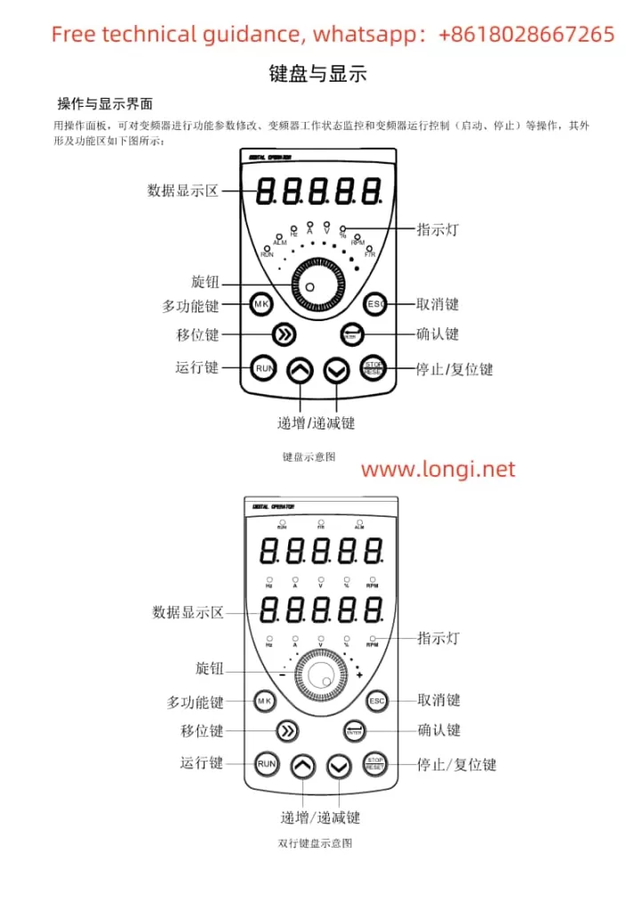
Function diagram of AT500 inverter operation panel buttons

II. Terminal Control and External Potentiometer Debugging Mode Setup

  1. Terminal Control Setup:
    • Guides users to enter the F0 parameter group and set F0.02 to 1 to enable terminal control.
    • Demonstrates how to assign functions to each input terminal through the F2 parameter group and explains wiring requirements.
  2. External Potentiometer Debugging Mode:
    • Teaches users to set F0.03 or F0.04 to AI3 (keyboard potentiometer) to adjust the output frequency by rotating the potentiometer knob.
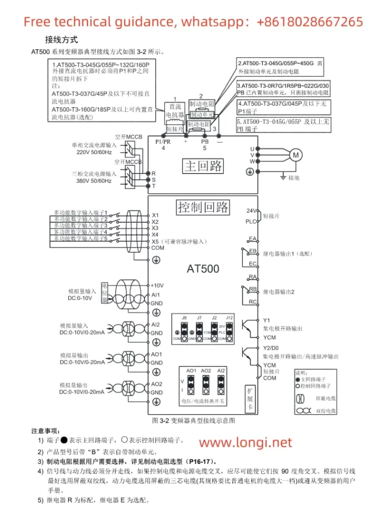
JACT AT500 inverter wiring diagram

III. Inverter Fault Code Classification and Troubleshooting Methods

  1. Overcurrent Faults (Err02-Err04):
    • Lists possible causes (output circuit short circuit, too short acceleration/deceleration time, etc.).
    • Provides solutions (check output circuit, adjust acceleration/deceleration time, etc.).
  2. Overvoltage Faults (Err05-Err07):
    • Analyzes fault causes (excessively high input voltage, external force during deceleration, etc.).
    • Offers remedies (adjust input voltage, eliminate external force during deceleration, etc.).
  3. Undervoltage Fault (Err09):
    • Describes fault causes (instantaneous power failure, low input voltage, etc.).
    • Suggests solutions (check input power supply, adjust voltage range, etc.).
  4. Overload Faults (Err10-Err11):
    • Indicates faults may be caused by excessive load, motor stall, etc.
    • Proposes reducing the load, checking the motor and mechanical conditions, etc.
  5. Input/Output Phase Loss Faults (Err12-Err13):
    • Analyzes fault causes (input power phase loss, faulty output wires or motor, etc.).
    • Offers advice on checking power and motor, troubleshooting peripheral faults, etc.
  6. Module Overheating Fault (Err14):
    • Explains fault causes (high ambient temperature, blocked air ducts, etc.).
    • Emphasizes the importance of reducing ambient temperature, cleaning air ducts, replacing fans, etc.
  7. Communication Fault (Err16):
    • Mentions possible causes (incorrect communication parameter settings, faulty communication cables, etc.).
    • Suggests checking communication parameters, cables, and the host computer.
Posted on Leave a comment

Comprehensive Guide to Resetting a Toshiba VFD (VF-A7)to Factory Default Settings

To ensure that a Toshiba Variable Frequency Drive (VFD) is restored to its factory default settings, follow this detailed, comprehensive guide that incorporates all provided images and specific requirements:

I. Understanding the KYP Parameter and Factory Reset

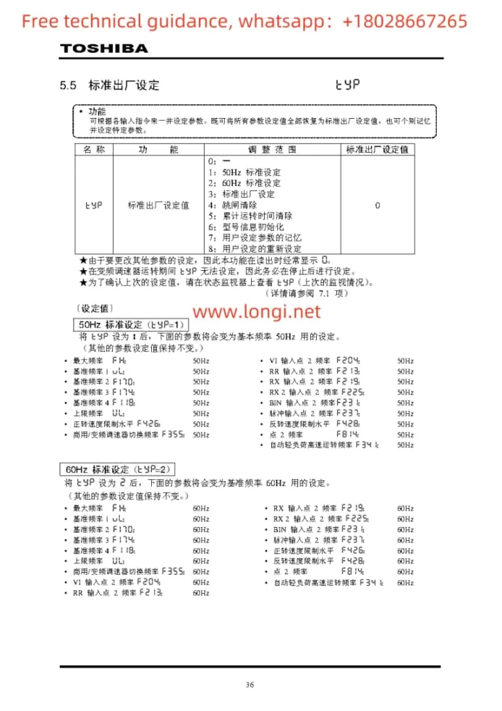
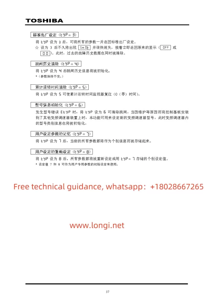
The KYP parameter is a special feature in Toshiba VFDs that allows users to reset the drive to its factory default settings. When the KYP is set to a specific value (usually “3”, but please refer to the VFD’s user manual for confirmation), all other parameters will be reset to their default states.

II. Recording Important Parameters (Optional Step)

Before performing the factory reset operation, it is recommended to record all important or customized parameter settings. This step is optional but highly advised so that these parameters can be restored if needed or referenced against the new settings.

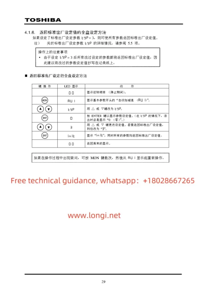
Basic Method for Toshiba VFD to Return to Factory Settings

III. Performing the Factory Reset Operation

  1. Initial Display:
    • The VFD’s LED display will show the current operating frequency (during stoppage).
  2. Entering Parameter Setting Mode:
    • Press the MON key, and the screen will display the first basic parameter, such as “Auto Acceleration/Deceleration (RU1)” or another parameter.
  3. Selecting the KYP Parameter:
    • Use the △ or ▽ keys to scroll through the parameter list until you find the KYP parameter.
  4. Viewing and Modifying the KYP Value:
    • Press the ENTER key to enter the KYP parameter setting interface.
    • The screen will now display the current setting of the KYP parameter (usually “0” or another non-specific value).
    • Use the △ or ▽ keys to change the KYP value to the specific value for executing the factory reset (usually “3”, but please confirm by referring to the user manual).
    • Press the ENTER key to confirm the modification.
  5. Confirmation and Initialization:
    • The screen will display “In it” or similar messaging, indicating that initialization is in progress.
    • All parameters will be reset to their factory default settings.
    • The initialization process may take some time, so please wait patiently.
  6. Restoring the Original Display:
    • Once initialization is complete, the LED display will return to its original state, such as showing the operating frequency.
KYP parameter description for Toshiba VFD

IV. Verifying the Factory Reset

After performing the factory reset operation, it is recommended to recheck all parameters to ensure they have been correctly reset to their factory default values. You can refer to the VFD’s user manual or contact technical support for detailed information on factory default values.

V. Important Considerations During Operation

  • Before performing the factory reset operation, ensure that the VFD is stopped and disconnected from the power source.
  • During the operation, please ensure that no other parameters are inadvertently modified, as this may affect the device’s performance.
  • If you encounter any doubts or uncertainties during the operation, press the MON key multiple times and restart from the basic parameter display.
  • If you are unsure how to perform the factory reset operation or encounter any issues, please contact Toshiba VFD technical support for assistance.
The KYP parameter of Toshiba VFD is set to 3

By following these steps, you can successfully reset your Toshiba VFD(VF-A7) to its factory default settings, restoring its original configuration. This will help ensure the VFD’s performance and stability, providing a solid foundation for its subsequent use.

The above is the method for resetting the VF-A7 series parameters of Toshiba VFD to factory values. It is derived from the summary and induction of the Toshiba VFD manual. If you need a complete Toshiba VFD manual, you can contact us directly or download it from Google drive:https://drive.google.com/file/d/1u2o8VJ3vwT1avatI4qsSRUVXlOebqgvY/view?usp=sharing

Posted on Leave a comment

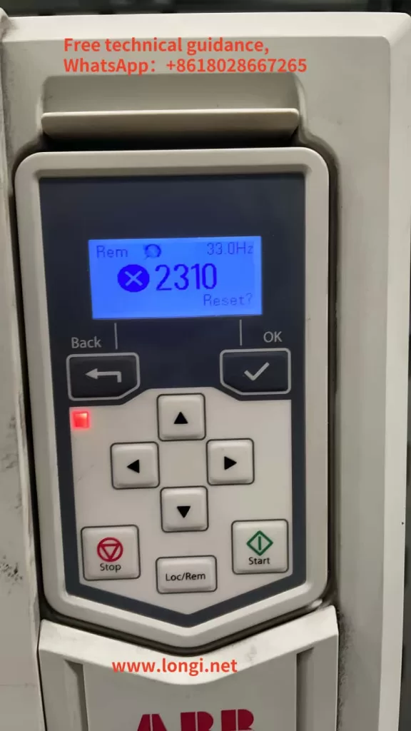
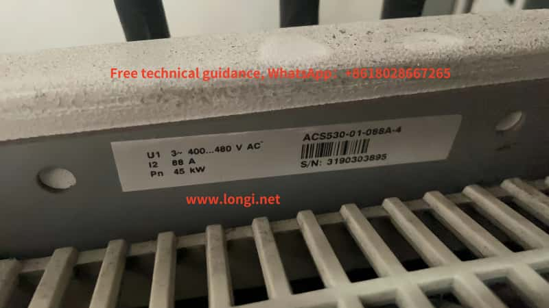
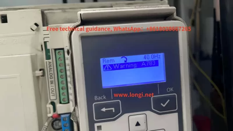
ABB Inverter ACS530 Series Alarm 2310: Causes and Solutions

The ACS530 series inverter from ABB, a leading player in industrial automation, is widely utilized across various industries. However, during operation, users may encounter various fault alarms, with alarm code 2310 being a common one, indicating an overcurrent fault. Based on the provided documentation, this article delves into the causes and corresponding solutions for ABB Inverter ACS530 series alarm 2310.

I. Causes of Alarm 2310

1. Excessive Motor Load

When the motor load exceeds its rated capacity, it can lead to a sharp increase in current, triggering the overcurrent protection. This may be due to an overly heavy load driven by the motor, mechanical jams, or motor stalls.

2. Incorrect Inverter Parameter Settings

The parameter settings of the inverter significantly impact its operational performance. Improper settings for acceleration time, deceleration time, or low current limits and overload protections can cause excessive current during motor startup or operation, resulting in an overcurrent alarm.

3. Unstable Power Supply Voltage

Fluctuations in power supply voltage directly affect the output voltage and current of the inverter. Unstable power supply can prevent the inverter from operating steadily, causing the output current to exceed normal ranges and trigger the overcurrent protection.

4. Motor or Cable Faults

Internal motor shorts, open windings, or grounding faults in motor cables can lead to excessive current. Additionally, contactors in the motor cable that are opening or closing can generate instantaneous high currents during switching, causing an overcurrent alarm.

5. Internal Inverter Faults

Damage or aging of internal components such as power modules, drive circuits, or current detection circuits in the inverter can result in unstable output currents, triggering an overcurrent alarm.

II. Solutions

1. Check Motor Load

First, inspect if the motor’s driven load is excessive. If so, attempt to reduce the load or replace the motor and inverter combination with higher capacities. Additionally, check for mechanical jams or stalls and address them promptly.

2. Review and Adjust Inverter Parameters

Examine the inverter’s parameter settings, particularly acceleration time, deceleration time, current limits, and overload protections. Ensure these settings are appropriate for the motor’s actual operational requirements. Adjust them if found to be incorrect.

3. Stabilize Power Supply Voltage

Use a multimeter or similar tools to check the stability of the power supply voltage. If significant fluctuations are present, implement measures to stabilize it, such as installing voltage stabilizers or UPS systems.

4. Inspect Motor and Cables

Examine the motor and motor cables for faults. Check for short circuits or open windings in the motor, verify the insulation resistance of the cables, and ensure no power factor correction capacitors or surge absorbers are present in the cables that could contribute to abnormal currents.

5. Check Internal Inverter Components

If all the above checks are normal, the overcurrent alarm may be due to internal inverter component damage. Contact professional technicians for inspection or replacement of faulty internal components.

III. Preventive Measures

To avoid the occurrence of ABB Inverter ACS530 series alarm 2310, adopt the following preventive measures:

Regular Inspections and Maintenance: Conduct periodic inspections and maintenance of the motor and inverter to ensure their smooth operation.

Appropriate Parameter Settings: When setting inverter parameters, base them on the motor’s actual conditions to prevent incorrect settings from causing overcurrent faults.

Stable Power Supply Voltage: Maintain stable power supply voltage to prevent its fluctuations from affecting the inverter’s performance.

Suitable Motor and Inverter Selection: Choose motors and inverters that match the actual load requirements to prevent overcurrent faults due to excessive loads.

In conclusion, ABB Inverter ACS530 series alarm 2310 is a critical fault alarm that requires attention. By thoroughly examining motor loads, adjusting inverter parameters, stabilizing power supply voltage, inspecting motors and cables, and checking internal inverter components, this issue can be effectively resolved, ensuring the inverter’s smooth operation. Furthermore, implementing preventive measures can reduce the likelihood of overcurrent faults and enhance the reliability and stability of the equipment.