
A set of hydraulic processing equipment in a factory suddenly broke down. A solenoid valve could not be powered, causing the hydraulic system to not work properly. After receiving a notice from the user requesting on-site maintenance, an intern from a mechanical and electrical technical school and an undergraduate majoring in automation set out to do the work.
The hydraulic station is controlled by 8 solenoid valves, which are powered by 24V DC and automatically controlled by PLC according to the process flow. Two interns circled the hydraulic system and PLC electric control cabinet for several times, and measured the normal resistance of the solenoid valve (labeled 8YV) coil, which was about tens of Ω . They judged that the solenoid valve was good, and asked the operator to operate the electric control cabinet. The other seven solenoid valves could work normally. However, the two ends of the 8YV coil could not get voltage and could not be attracted. The two interns roughly checked the circuit. The output contact of the PLC drives the intermediate relay KA8, which controls the action of the solenoid valve. The circuit is as shown below:
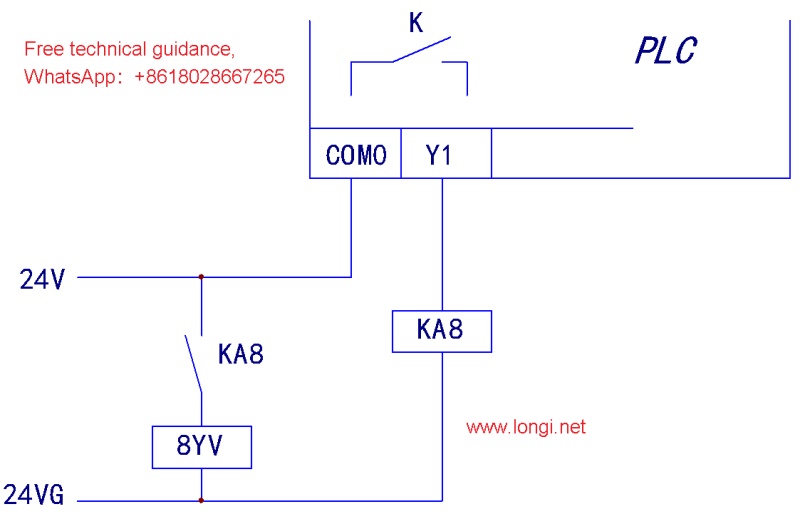
The circuit was basically clear, but the two students were confused about whether the fault was a PLC problem, an intermediate relay problem, or a circuit problem. In other words, how to check the PLC peripheral circuit fault when the machine was stopped. They wanted to measure the fault during the operation of the equipment, but they did not understand the equipment control process and were afraid of damaging the equipment, so they did not dare to operate. They were not sure whether it was a PLC or a PLC peripheral circuit problem. They did not know how to check it when the machine was stopped. After tinkering for an hour or two, they did not find any results and felt that their self-confidence had suffered a not-so-small blow.
The factory owner was a little anxious. If the repair was not done, the customer order would not be completed. He quickly called two veteran electricians and asked them to repair the equipment in a short time. The veteran electrician, Master Zhang, came up and scolded the two students: If the solenoid valve does not work, there are only two wires, just follow them and find the problem. How can it not be repaired? ! He asked the two students, have you learned PLC, have you learned control circuits? Both of them answered that they had learned PLC and control circuits. The two felt that they had learned well at that time, and one of them was in the top three in the class, a top student. The student said that he understood what he learned at that time, from the control principle to the circuit, everything was OK. How come it is useless all of a sudden? It is exactly: feeling high-energy in learning, but very low-energy in practice; academic performance is not bad, but it is not good when it comes to reality.
Master Zhang said, “Let me fix it while you watch. How difficult is it?” Master Zhang found a wire and introduced the 24V voltage directly to the two control leads of 8YV. He saw that the 8YV solenoid valve still did not work, and the lead was indeed broken. Master Zhang said, “Replace the wires. Replace the two leads of the solenoid valve, and it will be fixed. It’s very simple!”
The control line from the electric control cabinet was introduced into the workshop hydraulic station through dozens of meters of buried iron pipes. Master Zhang said, I know, there is a joint in the control line, it must be a bad contact. To repair it quickly, re-route two control leads of the 8YV solenoid valve, and solve the problem in ten minutes! A student asked: Do I need to measure it again? Master Zhang said, there is no need to measure, didn’t I just try it? In addition, two wires were pulled from the control terminal of the electric control cabinet and directly connected to 8YA. The power-on test, just as Master Zhang said, within ten minutes, the fault was eliminated.
At this time, the two students’ interest in learning was aroused, and they asked the old electrician Master Li: If you were asked to repair this fault, what would you do? Master Li was gentle and explained slowly: Master Zhang’s repair method is based on experience, and his inspection method is also more accurate and direct. He is familiar with the circuit of this equipment and can often solve the problem in a few minutes. You can’t reach this level in a short time. I rely on multimeter measurement, and after several inspection methods and steps, I find out the fault and solve the problem. My method is slower, but more universal and can be used anywhere. In fact, my method is more professional and classic.
What method do you use? The two students are getting impatient.
Master Li said: According to this fault situation, I should first turn off the control power supply of the electric control cabinet and measure the resistance of the two-wire terminal of 8YA from the control terminal. It is tens of Ω , indicating that the lead wire and the solenoid valve coil are basically normal. In fact, this measurement also found that the control lead wire of 8YA was broken, and the fault can be repaired by replacing the lead wire.
Student asked: If the lead wire and coil are good, why doesn’t 8YV work?
Master Li said: Next, we should check the peripheral control circuit at the PLC output end.
Master Li said: Find the two output control terminals YO and COM0 of the PLC. In fact, there is a normally open contact of a relay inside the two terminals. To put it simply, the PLC control terminal is a small switch. When the switch is closed, relay KA8 is energized, connecting the power supply of the 8YV coil and the solenoid valve is activated, right?
We can first short-circuit the two terminals YO and COM0 to observe whether KA8 works. If KA8 works normally but 8YV does not work, and then short-circuit the normally open control contacts of KA8, 8YA works normally, it means that KA8 is broken and the normally open contacts are in poor contact. If the two terminals YO and COM0 are short-circuited, the solenoid valve 8YV works normally, which means that the PLC output peripheral circuit is good. If the terminals YO and COM0 are short-circuited and KA8 does not work, check the 24V control power supply and leads.
Of course, on the electrical control cabinet side, you can short-circuit the YO and COM0 terminals and measure the 8YV terminal to see if there is 24V voltage to determine whether the PLC peripheral control circuit is normal.
In this way, by short-circuiting the two switch points, even if the fault of the PLC peripheral control circuit is exposed, it is not necessary to check the fault during the operation of the equipment. You have to find a way to change the normal state of the circuit, make it move, and expose the fault.
What if the PLC peripheral control circuit is fine, but the 8YV still doesn’t work? Two students asked.
Master Li explained slowly as usual: This may be a problem with the PLC and PLC input signal.
How to check it? The student asked again.
Master Li said: We need to let the operator try it out.
During operation, please pay attention. If the indicator light of the YO terminal can light up, but KA8 does not attract, it means that the contact of the internal relay of the PLC is poor. The PLC should be repaired or replaced. As shown in the circuit above, when the output indicator light of the Y0 terminal is on, you can measure that the voltage between the two terminals of YO and COM0 is 0V, indicating that the internal switch is connected; when the light is off, the voltage is 24V, indicating that the internal switch is disconnected. If the output indicator light of the Y0 terminal is on, but the voltage is still 24V, the contact of the internal relay of the PLC must be damaged.
During the operation, the output indicator light of the Y0 terminal is always off. When the PLC program is running normally (such as other controls are normal in this example), it may be that the signal of the PLC input terminal is not input normally, or the state is wrong, and the conditions of YO output cannot be met. At this time, you can use a laptop to call up the PLC internal program, monitor the program running, find out the conditions that meet the Y0 output and various conditions, and then find out which input signal is abnormal, such as poor contact of the normally closed point of the external limit switch, etc., and the fault can be eliminated.
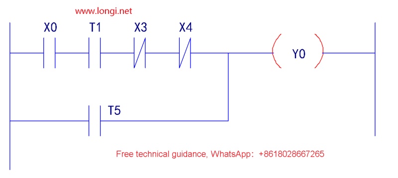
In the figure above, XO, T1, X3, X4, and T5 can all be called conditional contacts of YO. Let’s ignore T5 for now. For the control of YO, only when the XO (input condition) and T1 (after the delay time is up) contacts are connected, and the X3 and X4 contacts remain static, can YO meet the conditions for powering on. Find out which of these four contacts is not met, find the cause of the fault, and then repair it. If you check that the status of the X0, X3, and X4 contacts are all correct, and look at the PLC input terminal status indicator, X0 is on, and X3 and X4 are off, then three of the four conditions have been met, and only the T1 condition is not met. Further search for the control program segment for the T1 coil in the program, and then check the conditions for meeting the power-on condition of T1, step by step, and find the cause of the fault.
The external input signal of PLC, such as limit switch, may be installed in a place that is not easy for us to touch. Its closing and opening are not easy to operate. At this time, you can also take the method of short-circuiting YO and COM0 terminals, artificially short-circuiting the PLC input terminals, forming an input signal, satisfying the YO power-on condition, and finding out the fault. For example, short-circuit X0 and COM terminals to see if the input indicator light is on and whether the output is moving. If the input terminal status indicator light is not on, check the input terminal 24V power supply is normal, then the internal input circuit of PLC is broken.
During the maintenance process, do not forget to communicate with the operator and electrician in a timely manner. They are familiar with the operation process. You may have searched for a long time, but they may not be able to tell you the fault with just one word of reminder. For example, they mentioned that YO can only act after Y1 output delays for 10 seconds, which makes you understand that YO can only act after Y1 acts. As a result, the problem is found in the control circuit of Y1. This can greatly improve the maintenance efficiency.
When Master Li finished speaking, the two students were convinced and felt that this job was not that difficult. They were full of confidence. They learned things that they could not learn in school from this maintenance example and from the two old electricians. They felt that they had gained a lot. They felt that if the teachers who led the internship class could teach like Master Li, they would be very lucky.