
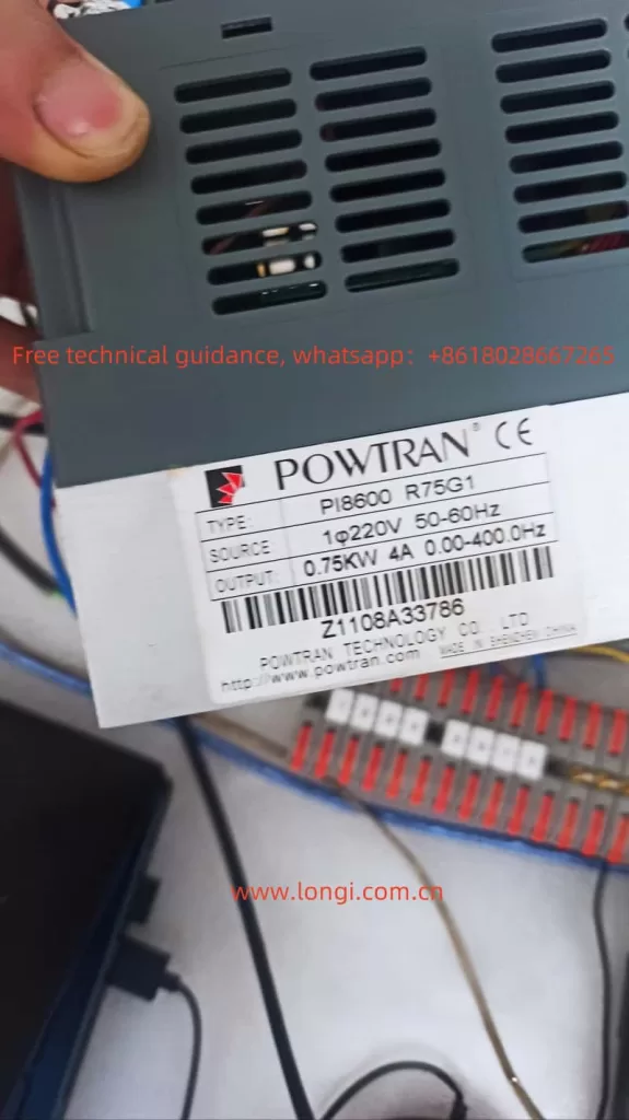
I. Usage Instructions for Powtran PI8600 Series Inverter
1. Panel Operation Setup
The panel operation of the Powtran PI8600 series inverters is straightforward. Here’s how to set up panel start, panel speed regulation, restore factory settings, set passwords, and remove passwords:
Panel Start and Speed Regulation:
- Entering Parameter Setting Mode:
- Press the
PRGbutton to enter the parameter group query state. - Use the potentiometer to switch to the
F00-63basic function group. - Press the
PRGbutton again to enter the parameter query state within theF00-63group. - Switch to
F02(Frequency Main Setting Mode) using the potentiometer. - Press the
PRGbutton to enter the parameter modification state forF02. - Set
F02to4(Keyboard Potentiometer Given) using the potentiometer andSETbutton.
- Press the
- Adjusting Speed:
- Rotate the potentiometer on the panel to adjust the set frequency in real-time, which will also adjust the motor speed.
Restoring Factory Settings:
- In the monitoring state, press the
PRGbutton to enter the parameter group query state. - Use the potentiometer to switch to the
y00-23system function group. - Press the
PRGbutton to enter the parameter query state within this group. - Switch to
y00(Reset System Parameters) using the potentiometer. - Press the
PRGbutton to enter the parameter modification state. - Set the parameter to
5to reset the system parameters to factory defaults using the potentiometer andSETbutton.
Setting and Removing Passwords:
- Setting a Password:
- Enter the system function group (
y00-23) as described above. - Switch to
y15(User Decode Input) to set the password. - Enter the desired password using the potentiometer and
SETbutton.
- Enter the system function group (
- Removing a Password:
- Again, enter the system function group.
- Switch to
y16(User Password Input). - Enter the current password followed by the new password (all zeros to remove the password) using the potentiometer and
SETbutton.
2. Fault Code Enumeration and Analysis
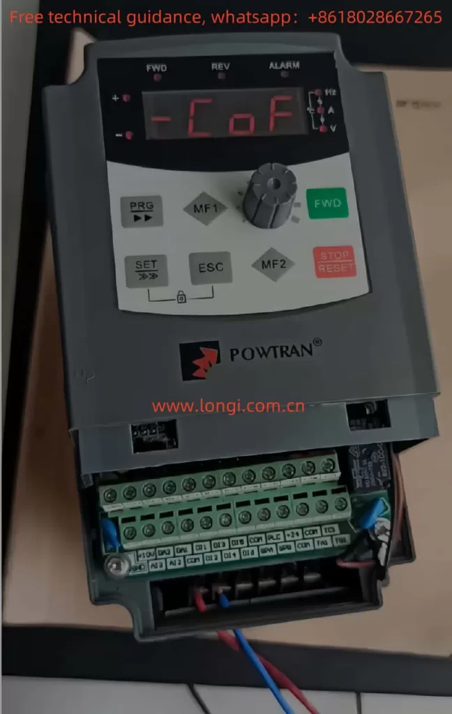
Fault Code COF – Communication Failure:
Symptoms:
- The inverter fails to communicate properly with external devices or the control panel.
Possible Causes:
- Poor connection at the keyboard interface or control board.
- Faulty keyboard cable or crystal connector.
- Damaged control board or keyboard hardware.
- Excessive length of the keyboard cable causing interference.
Solutions:
- Check and tighten all connections at the keyboard interface and control board.
- Replace the keyboard cable or crystal connector if damaged.
- Inspect the control board and keyboard for any signs of damage. Replace if necessary.
- If using a long keyboard cable, consider using a shielded cable or reducing the cable length to minimize interference.
Other Common Fault Codes:
- OC: Overcurrent. Check the motor and cable connections, and ensure the motor is not overloaded.
- OU: Overvoltage. Verify the input voltage and consider installing a voltage stabilizer.
- LU: Undervoltage. Check the power supply and ensure it meets the inverter’s voltage requirements.
- OL: Overload. Reduce the load on the motor or adjust the overload protection parameters.
By following the above instructions, users can effectively operate the Powtran PI8600 series inverters, troubleshoot common issues, and maintain optimal performance.