The user went to a hardware and electrical store to buy a thermometer for automatic temperature control of the material tank in the production workshop. The control requirements put forward by the user are: when the temperature of the material tank is as low as 25 º C, start the boiler fan to heat it up; when the temperature of the material tank rises to 32 º C, stop the fan. The temperature is not required to be precisely controlled at one point, but it can be roughly maintained between 25 º C and 32 º C. In this way, the fan does not need to be started frequently and run for a long time, and the power saving effect will be very good. It is said that after searching several electrical and mechanical stores, no suitable temperature control meter can be found. If it can be solved here, it doesn’t matter if the price is a little higher, and five or six units can be purchased at once.
The father and son run the hardware and electrical store. The father is an old electrician, and the son is a student of the Department of Mechanical and Electrical Engineering, with top grades. The father and son were excited and decided to make this deal. The temperature controllers in the store generally have the following functions, see the wiring diagram below:
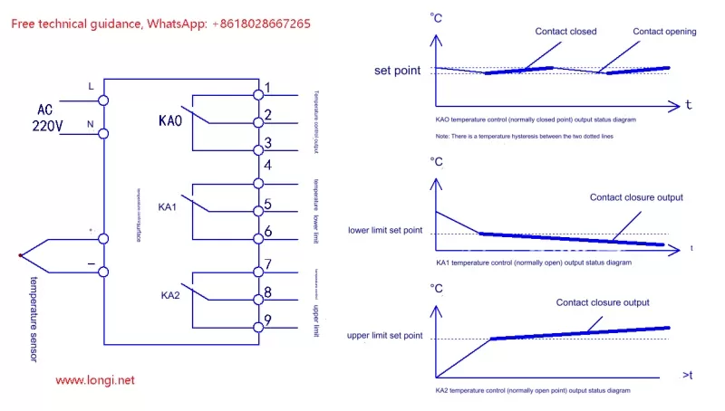
From the wiring diagram, the temperature controller has three groups of output control contacts. KA0 is the control temperature output. If its normally closed point is used as the control output, the contact closing and opening action area is near the temperature setting point. For example, if the setting point is 25 º C, when the measured temperature rises to 25 º C, the normally closed contact is disconnected, and when the measured temperature drops to 23 º C, the contact is closed. This control method belongs to “point” control. The action of the relay tracks a temperature setting point. Although in order to avoid frequent switching at one point, there is often a temperature hysteresis value in the middle, such as 2 º C between 23 º C and 25 º C. Some models have this hysteresis fixed, while others are adjustable, but the temperature difference adjustment range is not too large. Obviously, the control output contact of KA0 cannot meet the control requirements put forward by users.
Let’s look at the output contact of KA1, which is the lower limit control output. It is also output based on a “temperature point”. When the measured temperature reaches the preset lower limit, KA1 will act. As long as it is within the lower limit, KA1 will maintain the output. Only when the measured temperature is higher than the lower limit setting point, KA1 will lose power and the contact will be released. The control requirements cannot be achieved by relying solely on the control contacts of KA1. The output contact of KA2 is the upper limit setting point. Its control principle is the same as that of KA1. It can also be regarded as a “point” control and cannot complete the control task independently.
My son suddenly had an idea: Is it possible to combine the lower limit and upper limit control outputs to meet the control requirements proposed by the user?
Dad nodded approvingly: Okay, I thought so too, let’s try to analyze it.
See the following control state diagram of KA1 and KA2 output combination and user control requirement diagram:
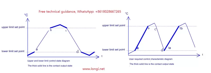
My son said: By connecting the normally closed points of the two relays KA1 and KA2 in series, the fan can be powered on and operated in the area where the two relays are not operating. That is, the fans in sections a and b in the figure can be powered on and operated. Doesn’t this meet the requirements?
Dad said: It seems not to work. The fan is also powered in sections c and d. The fan is powered and running most of the time. The fan stops only when it is outside the upper and lower limits. It still doesn’t work to use the two contacts directly. The user’s requirements are shown in the right figure of Figure 2. Only the thick line segments (a, b/1a, 1b) in the right figure are the time for the fan to run. When the detected temperature reaches the lower limit, the fan runs, and when it reaches the upper limit, the fan stops; then the temperature drops and reaches the lower limit again, the fan starts running again. The fan does not run at one “point”, but only runs on “segments” a and b, achieving a good power saving effect.
My son said: I didn’t notice the c and d segments in the left figure. It’s not possible. But we can use the upper and lower limit contact outputs and add an external control circuit to achieve it. This additional circuit should not be difficult to make.
The father wanted to test his son’s level, so he said: How about this, let’s both make an external control circuit, and see who’s circuit is simpler and more reasonable, and then we’ll use their circuit, okay?
The son knew that his father wanted to test his ability and it was also a small challenge for him. He thought that since he had worked on some complicated electromechanical control circuits, this small circuit should be no problem for him. So he readily agreed.
It seems to be a simple thing to think about, but in practice, this small function is not so easy to achieve. It seems that it cannot be completed with two additional relays, and the circuit is too complicated to use three relays. According to my father’s idea, it should be possible to achieve it with two additional relays. It seems that it cannot complete the task if one contact of KA1 and KA2 is used.
The son spent half a day drawing several diagrams, optimizing and simplifying the circuit, and finally succeeded through wiring tests. However, the analysis from the control principle was a bit confusing. The father frowned and thought about it at first, but suddenly grabbed a pen and drew a wiring diagram in no time. Without wiring tests, he announced that the circuit would definitely work.
The control circuit diagram made by the father and son is as follows:
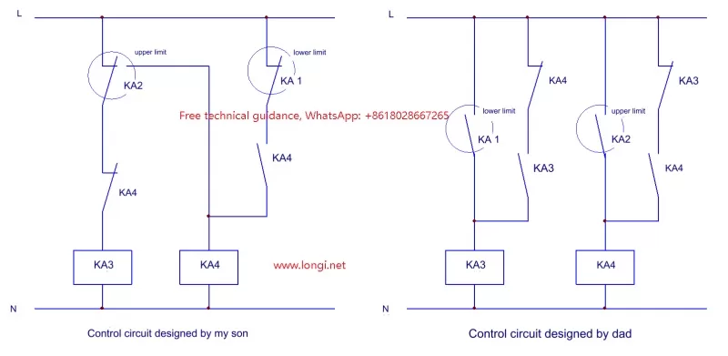
In the figure, KA1 and KA2 are the upper and lower limit signal output relays inside the temperature control meter, KA3 and KA4 are external relays, and KA3 provides control signal output. The control circuit designed by my son uses the normally open and normally closed contacts of the upper limit relay, the normally closed contacts of the lower limit relay, and two sets of contacts of KA4. The control process is as follows: After the equipment is powered on, the normally closed contact circuit of KA2 and KA4 provides power to the KA3 coil, KA3 is energized, the fan runs, and the discharge tank begins to heat up; when the temperature reaches the upper limit, the normally closed point of KA2 is disconnected, the normally open point is connected, KA3 loses power, and at the same time KA4 is energized for self-protection, the fan stops, and the discharge tank begins to cool down; due to the self-protection effect of KA4, when the temperature drops below the upper limit, KA4 maintains an energized state through the normally closed point of KA1 and its own self-protection contact, and KA3 maintains a de-energized state, and the temperature of the discharge tank continues to drop until it reaches the lower limit of the temperature, the KA1 lower limit relay is activated, the KA4 self-protection circuit is disconnected, KA4 loses power, KA3 is energized again, and the fan runs.
The control circuit designed by my father seems to be simpler. The circuit is clear in principle and is more convenient for analyzing the control process: when the temperature of the unloading tank reaches the lower limit, KA3 is energized and forms a self-protection (self-locking) circuit through the normally closed point of KA4 and the normally open point of KA3, and the fan runs; when the temperature reaches the upper limit, the normally open point of the upper limit relay KA2 is connected, KA4 is energized, and while disconnecting the self-locking circuit of KA3, it forms its own self-locking circuit through the normally closed point of KA3 and the normally open point of KA3. KA4 remains energized, KA3 remains de-energized, and the fan stops; when the temperature drops to the lower limit of the temperature, the relay KA1 is activated, KA3 is activated, and while disconnecting the self-locking circuit of KA4, KA3 forms its own self-locking circuit, and the fan starts running again.
The focus of control requirements is to meet two conditions:
1. Once KA3 and KA4 are powered, they can be self-protected (self-locked);
2. When two relays are powered on for self-protection, the self-protection circuit of relay B must be disconnected to make it lose power. The same is true in reverse.
This control method is not conventional temperature point control, but temperature range control, which can be regarded as a special application.
Both the son’s and the father’s circuits can accomplish the task, and use the same number of contacts, but the father’s circuit is easier to understand and more classic. The son’s circuit also accomplishes the task well, which is rare.
Dad said: I thought of these two conditions, and based on these conditions, I formed this circuit in the computer. It was a waste of effort before the logical relationship of the circuit was clear.
Although the son has figured out the circuit, it seems that his father is still better in terms of circuit routing and principle analysis. His father’s circuit is more “smooth”, while my own circuit is a bit tortuous. When you make a circuit yourself, you should be better at analyzing the logical relationship and take a “smooth” path to make the circuit more optimized and reasonable.
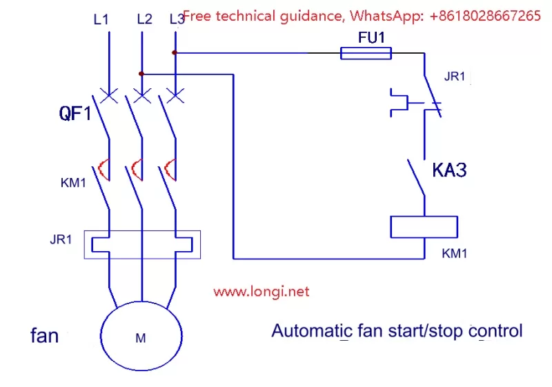
The fan control wiring diagram is as follows:
In the figure, KA1 and KA2 are the upper and lower limit signal output relays inside the temperature control meter, KA3 and KA4 are external relays, and KA3 provides control signal output. The control circuit designed by my son uses the normally open and normally closed contacts of the upper limit relay, the normally closed contacts of the lower limit relay, and two sets of contacts of KA4. The control process is as follows: After the equipment is powered on, the normally closed contact circuit of KA2 and KA4 provides power to the KA3 coil, KA3 is energized, the fan runs, and the discharge tank begins to heat up; when the temperature reaches the upper limit, the normally closed point of KA2 is disconnected, the normally open point is connected, KA3 loses power, and at the same time KA4 is energized for self-protection, the fan stops, and the discharge tank begins to cool down; due to the self-protection effect of KA4, when the temperature drops below the upper limit, KA4 maintains an energized state through the normally closed point of KA1 and its own self-protection contact, and KA3 maintains a de-energized state, and the temperature of the discharge tank continues to drop until it reaches the lower limit of the temperature, the KA1 lower limit relay is activated, the KA4 self-protection circuit is disconnected, KA4 loses power, KA3 is energized again, and the fan runs.
The control circuit designed by my father seems to be simpler. The circuit is clear in principle and is more convenient for analyzing the control process: when the temperature of the unloading tank reaches the lower limit, KA3 is energized and forms a self-protection (self-locking) circuit through the normally closed point of KA4 and the normally open point of KA3, and the fan runs; when the temperature reaches the upper limit, the normally open point of the upper limit relay KA2 is connected, KA4 is energized, and while disconnecting the self-locking circuit of KA3, it forms its own self-locking circuit through the normally closed point of KA3 and the normally open point of KA3. KA4 remains energized, KA3 remains de-energized, and the fan stops; when the temperature drops to the lower limit of the temperature, the relay KA1 is activated, KA3 is activated, and while disconnecting the self-locking circuit of KA4, KA3 forms its own self-locking circuit, and the fan starts running again.
The focus of control requirements is to meet two conditions:
1. Once KA3 and KA4 are powered, they can be self-protected (self-locked);
2. When two relays are powered on for self-protection, the self-protection circuit of relay B must be disconnected to make it lose power. The same is true in reverse.
This control method is not conventional temperature point control, but temperature range control, which can be regarded as a special application.
Both the son’s and the father’s circuits can accomplish the task, and use the same number of contacts, but the father’s circuit is easier to understand and more classic. The son’s circuit also accomplishes the task well, which is rare.
Dad said: I thought of these two conditions, and based on these conditions, I formed this circuit in the computer. It was a waste of effort before the logical relationship of the circuit was clear.
Although the son has figured out the circuit, it seems that his father is still better in terms of circuit routing and principle analysis. His father’s circuit is more “smooth”, while my own circuit is a bit tortuous. When you make a circuit yourself, you should be better at analyzing the logical relationship and take a “smooth” path to make the circuit more optimized and reasonable.
The fan control wiring diagram is as follows: