Repair Guide for INVT G9 Series Frequency Converter “Crash” Fault
When dealing with a reported “crash” fault in an INVT G9 series frequency converter, a systematic approach to diagnosis and repair is crucial. This article outlines a step-by-step process based on user feedback, detailed inspection, and successful repair.
User Feedback and Initial Observations
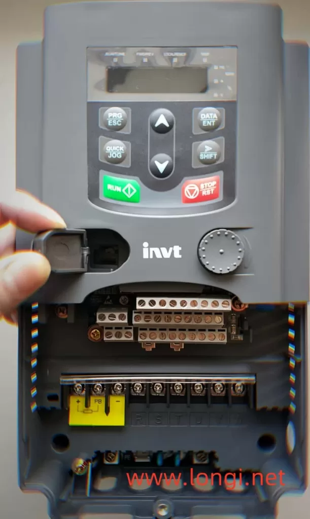
The user reported that the frequency converter was not operational at the time of the incident, but other machines on the same three-phase power supply experienced abnormalities, leading to a short circuit and tripping. Consequently, the power switch for the frequency converter also tripped. Upon attempting to reset the power switch, it was discovered that the operation panel was no longer displaying any information, prompting the need for repair.
Detailed Inspection and Fault Identification
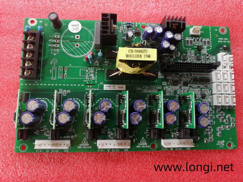
Upon inspecting the frequency converter, an open circuit was found between the R, S, T terminals and the main DC circuit (P and N). Further disassembly revealed that the copper foil strip connecting to the module had been damaged by an arc. Testing confirmed a short circuit at the three-phase power supply terminal of the module.
Root Cause Analysis
The root cause of the malfunction was traced back to instantaneous short circuits and tripping of other load branches in the power supply, which induced abnormal voltage spikes in the three-phase power supply. These dangerous voltage levels caused the rectifier circuit in the frequency converter module to break down and short circuit. The resulting strong arc burned the copper foil strip and triggered the power switch to trip.
Repair Plan
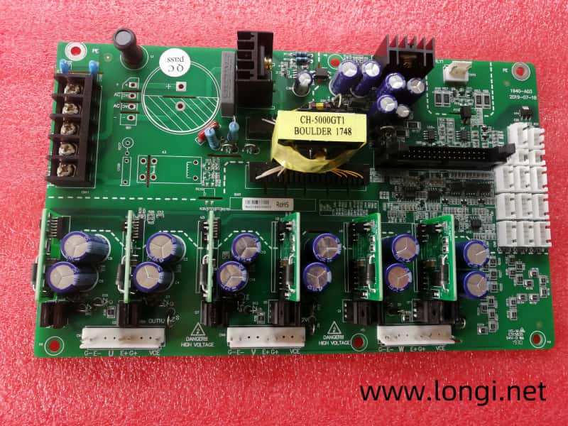
Fortunately, the inverter part of the module was still functional, with no signs of bulging or deformation. Therefore, the decision was made to cut off the damaged rectification part of the module and install an additional three-phase rectification bridge. This low-cost repair plan allowed for the reuse of the original three-phase inverter circuit in the module.
Inspection and Troubleshooting
To prevent further abnormalities, the power supply to the inverter section of the module was cut off. A 500V DC voltage was applied from an external repair power supply, but the operation panel displayed “H.00,” and all operations were ineffective. Based on experience, this indicated that the module’s short circuit detection function had activated, causing the CPU to reject all operations.
Further inspection revealed that the overcurrent signals in the fault signal collection and processing circuit were all negative, whereas they should have been positive under normal conditions. Tracing the current detection circuit, it was found that an incorrect overcurrent signal was being output. By disconnecting the overcurrent fault signal, the operation panel’s parameter settings returned to normal, but the start/stop operation still had no response.
Additional Fault Signals and Resolution
Suspecting that there might be other fault signals causing the frequency converter to remain in protection mode, the voltage at the module’s thermal alarm terminal was measured and found to be 3V, lower than the normal 5V. It was hypothesized that the damaged rectification circuit might be outputting a thermal alarm signal. By cutting off the copper foil strip connected to the thermal alarm, the start/stop operation on the operation panel became effective.
Protection Sequence and Final Repairs
The protection sequence of the INVT G9/P9 frequency converter is designed to ensure safe operation. If a fault is detected in the power inverter output section during power-on detection, the SC – output short circuit fault code will be displayed, and all operations will be rejected. Similarly, if an overcurrent signal is detected, “H.00” will be displayed, and all operations will be halted. When a thermal alarm signal is detected, most operations can be performed, but the startup operation is rejected to prevent overheating.
To complete the repair, the damaged copper foil strip lead of the three-phase power supply was cut off, cleaned, and properly insulated. An external three-phase rectifier circuit was connected, and its DC output was introduced to the P and N terminals. Additionally, a thermal protection circuit was installed using a 60℃ normally closed thermal relay, which is connected in series with an NPN type transistor base to the 5V ground circuit. This ensures that the module does not overheat and burn, providing an additional layer of safety.
By following this structured approach, the INVT G9 series frequency converter was successfully repaired, restoring it to full functionality.