
I. JOG Jogging Operation Process
The JOG mode allows users to directly control the start, stop, and reverse of the servo motor through buttons, commonly used for manual debugging and positioning. Below are the specific steps for JOG jogging operation:
- Connect Control Signals:
- Ensure that the control signal cable CN1 of the servo driver is correctly connected to the corresponding controller or manual operation panel.
- Set the Servo Enable (SON) to OFF, CCW Drive Inhibit (FSTP) and CW Drive Inhibit (RSTP) both to ON, or disable the drive inhibit function using parameter PA20.
- Power On the Control Circuit:
- Turn on the control circuit power supply of the servo driver (note that the main circuit power supply should remain off for now).
- The display of the servo driver will light up. Check for any alarm messages, and if any, inspect the connection wiring.
- Set Control Mode:
- Enter the parameter setting interface and set the Control Mode Selection (Parameter No. 4) to JOG mode (value 3).
- Power On the Main Circuit:
- After confirming no alarms or abnormalities, turn on the main circuit power supply.
- Set the Servo Enable (SON) to ON, and the motor will enter an excited state but remain at zero speed.
- Perform JOG Operation:
- In JOG mode, press and hold the Up key (↑) to make the motor run forward at the preset JOG speed (set in Parameter No. 22); release the key, and the motor will stop and remain at zero speed.
- Press and hold the Down key (↓) to make the motor run reverse at the preset JOG speed; release the key, and the motor will stop and remain at zero speed.
II. Position Mode Operation Process
The position mode allows users to control the precise position of the servo motor by sending position commands. Here are the specific steps for position mode operation:
- Set Basic Parameters:
- Ensure the Servo Enable (SON) is set to OFF, and CCW Drive Inhibit (FSTP) and CW Drive Inhibit (RSTP) are both set to ON.
- Enter the parameter setting interface and set the Control Mode Selection (Parameter No. 4) to Position Mode (value 0).
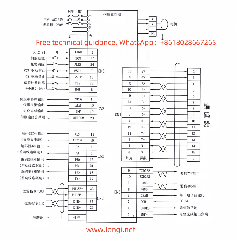
- According to the output signal method of the controller, set Parameter No. 14 (Position Command Pulse Input Mode) and the appropriate electronic gear ratio (No. 12 and No. 13).
- Connect Position Command Signals:
- Connect the position controller’s output signals to the corresponding position command input terminals of the servo driver (e.g., CN1-22/5/14/23 pins).
- Power On and Start:
- Turn on both the control circuit and main circuit power supplies. After confirming no alarms or abnormalities, set the Servo Enable (SON) to ON, and the motor will enter an excited state.
- Operate the position controller to send position commands to the servo driver, driving the motor to move precisely to the designated position.
III. Speed Mode Operation Process
The speed mode allows users to control the rotation speed of the servo motor by sending speed commands. Here are the specific steps for speed mode operation:
- Set Basic Parameters:
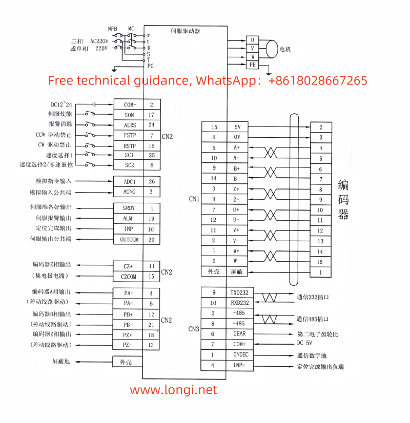
- Ensure the Servo Enable (SON), Speed Selection 1 (SC1), and Speed Selection 2 (SC2) are all set to OFF, and CCW Drive Inhibit (FSTP) and CW Drive Inhibit (RSTP) are also OFF, or use parameters for direct control.
- Enter the parameter setting interface and set the Control Mode Selection (Parameter No. 4) to Speed Mode (value 1).
- Set the internal speed parameters No. 24 to No. 27 as needed.
- Connect Speed Command Signals:
- Connect the output signals of the speed controller to the speed command input terminals of the servo driver (e.g., through control terminal CN2 or internal speed selection).
- Power On and Start:
- Turn on both the control circuit and main circuit power supplies. After confirming no alarms or abnormalities, set the Servo Enable (SON) to ON, and the motor will enter an excited state.
- Operate the speed controller to send speed commands to the servo driver, driving the motor to rotate at the commanded speed.
IV. Fault Codes and Solutions
- Err-01: IPM Module Fault
- Cause: Circuit board failure, low supply voltage, damaged motor insulation, etc.
- Solution: Check the driver connections, confirm normal supply voltage, and replace the faulty driver or motor.
- Err-03: OCU Overcurrent
- Cause: Short circuit in U, V, W phases of the driver, poor grounding.
- Solution: Check the driver connections, ensure proper grounding, and replace the faulty driver.
- Err-07: Encoder Fault
- Cause: Incorrect encoder wiring, encoder damage, or faulty cable.
- Solution: Check encoder wiring, replace the encoder or cable.
- Err-08: Speed Deviation
- Cause: Excessively high input command pulse frequency, improper acceleration/deceleration time constants.
- Solution: Correctly set the input pulse frequency and acceleration/deceleration time constants, check encoder status.
- Err-09: Position Deviation
- Cause: Incorrect position command, encoder damage.
- Solution: Check position commands and encoder status, reset position parameters.
By following these steps and solutions, users can effectively operate the KaiZheng Servo C&B series servo driver in JOG mode, position mode, and speed mode, and promptly address potential fault codes for better Google indexing.