
I. Description of Operation Panel Functions and Process for Restoring Factory Default Settings
- Description of Operation Panel Functions
The operation panel of Shihlin VFD SS series is powerful, facilitating user settings and monitoring. The operation panel mainly includes the following function keys and indicators:
RUN/STOP Key: Used to start and stop the VFD.
Frequency Adjustment Knob: Used to manually adjust the output frequency of the VFD.
Mode Switch Key: Used to switch between different operation modes, such as PU mode, JOG mode, external mode, etc.
Monitor/Set Key: Used to switch between monitor mode and set mode.
LED Indicators: Including running indicator, frequency monitor indicator, voltage monitor indicator, etc., used to indicate the current status of the VFD.
- Process for Restoring Factory Default Settings
If you need to restore the VFD parameters to their factory defaults, follow these steps:
Switch to Monitor Mode: Press the Monitor/Set key to ensure the VFD is in monitor mode.
Read Parameter Pr998: Enter the parameter setting mode on the operation panel, find parameter Pr998, and read its current value.
Write Parameter Pr998: Write the read Pr998 value again. At this point, the VFD will automatically initialize the parameters, and all parameters will be restored to their factory defaults.
Restart the VFD: To ensure the parameters are successfully restored, it is recommended to restart the VFD.

II. Terminal Start and External Potentiometer Speed Adjustment Wiring and Parameter Debugging
- Terminal Start Wiring and Parameter Debugging
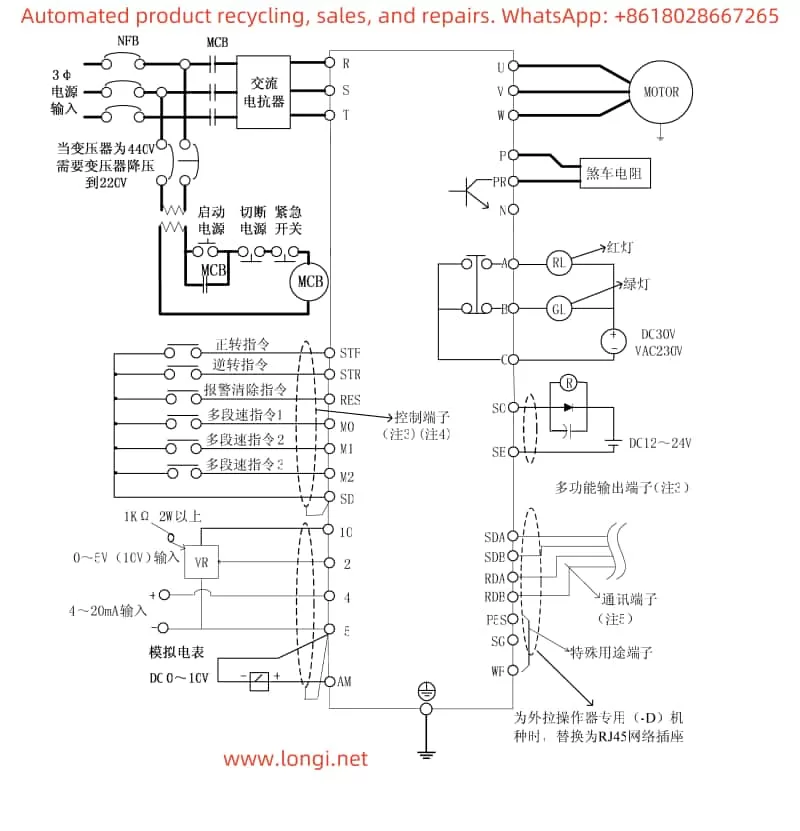
If you need to start the VFD via terminal, you need to connect the external control signal to the corresponding control terminal of the VFD. Taking the STF (forward start) terminal as an example, the wiring and parameter debugging process is as follows:
Wiring: Connect the positive pole of the external control signal to the STF terminal, and the negative pole to the common terminal SD.
Parameter Settings:
Enter the parameter setting mode, set Pr79 to 2 (external mode).
Set parameters such as start frequency (Pr13) and upper limit frequency (Pr1) as needed.
Ensure that the STF terminal function is correctly set (default is forward start function).
- External Potentiometer Speed Adjustment Wiring and Parameter Debugging
If you need to adjust the output frequency of the VFD through an external potentiometer, you need to connect the output signal of the potentiometer to the analog signal input terminal of the VFD. Taking a 0~10V voltage signal as an example, the wiring and parameter debugging process is as follows:
Wiring: Connect the positive output of the potentiometer to the AI1 (2-5) terminal of the VFD, and the negative output to the common terminal GND.
Parameter Settings:
Enter the parameter setting mode, set Pr73 to 1 (select 0~10V voltage signal input range).
Set Pr38 to the desired voltage-frequency conversion relationship, for example, when the potentiometer outputs 10V, the VFD outputs a frequency of 50Hz.
Set Pr79 to a suitable operation mode, such as external mode or mixed mode.
Ensure that other relevant parameters (such as acceleration and deceleration time, torque compensation, etc.) have been set according to actual needs.
III. Analysis and Solutions for Fault Alarms
The Shihlin VFD SS series may encounter various fault alarms during operation. Below are some common fault alarm codes, their analysis, and solutions:
ERR (Error):
Cause: May be caused by insufficient power supply voltage, the RESET terminal being connected, poor contact between the operator and the main unit, internal circuit failure, or CPU malfunction.
Solution: Check if the power supply voltage is normal; disconnect the reset switch; ensure good connection between the operator and the main unit; if the problem persists, the VFD may need to be replaced or restarted.
OC1 (Overcurrent During Acceleration), OC3 (Overcurrent During Deceleration):
Cause: Usually caused by excessive load, too short acceleration/deceleration time, or abnormal regenerative braking resistor.
Solution: Check if the load is excessive and reduce it appropriately; extend the acceleration/deceleration time; check if the regenerative braking resistor is connected properly and has the correct resistance.
OV2 (Overvoltage at Constant Speed):
Cause: May be caused by excessive voltage between terminals P-N.
Solution: Check if a regenerative braking resistor is connected between terminals P-PR and if the connection is normal; if regenerative function is not needed, short-circuit between P-PR.
THT (IGBT Module Overheat):
Cause: The IGBT module temperature is too high.
Solution: Check if the ambient temperature around the VFD is too high; ensure good heat dissipation of the VFD; check if the setting of the electronic thermal relay capacity is reasonable.
BE (Brake Transistor Abnormal):
Cause: External motor thermal relay actuation.
Solution: Check if the capacity of the external thermal relay matches the motor capacity; reduce the load to avoid frequent actuation of the thermal relay.
By carefully reading this user manual and following the above operation guide, users can better understand and use the Shihlin VFD SS series, ensuring normal operation and efficient working of the equipment.