Shenzhen SHZHD Inverter V680 Series Operation Guide and E10 Fault Handling
I. Operation Panel Function Introduction, Parameter Factory Reset, and Password Management

1. Operation Panel Function Introduction
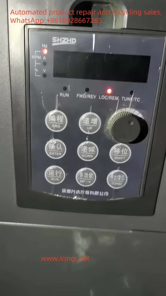
The operation panel of the Shenzhen SHZHD Inverter V680 series provides an intuitive operation interface, allowing users to set various parameters and operate the inverter through buttons and displays on the panel. The main functions of the panel include:
- Display Area: Displays current set frequency, output frequency, current, voltage, and other parameters.
- Function Keys: Such as MENU, ENTER, △, ▽, used for entering menus, confirming settings, and adjusting parameters.
- Run Key: Starts and stops the inverter.
- Fault Indicator: When the inverter malfunctions, the corresponding indicator light will illuminate, prompting the user to check the fault.
2. Parameter Factory Reset
To restore the inverter’s parameters to their factory defaults, follow these steps:
- Enter the menu interface and find the “Parameter Initialization” option.
- Select “Restore Factory Parameters” and confirm execution. At this point, all parameters except motor parameters will be restored to their factory settings.
3. Adding and Removing Passwords
To protect parameters from being modified casually, users can set passwords for the inverter.
- Adding a Password: Enter the “User Password” setting, input the desired password, and confirm to save.
- Removing a Password: Re-enter the “User Password” setting and set the password to 0 to remove password protection.
II. Torque Control and Vector Control
1. Torque Control
Torque control is a special control mode that allows users to directly set the output torque of the inverter instead of indirectly controlling the torque by setting the frequency. This control mode is very useful in situations where precise control of the load torque is required.
- Setting Method: First, select “Torque Control” in the control mode. Then, choose the torque setting source through the corresponding parameter (such as A0-01), which can be the keyboard, analog input, communication, etc. Finally, set the desired torque value through parameters such as A0-03.
2. Vector Control
Vector control is a high-performance control method that achieves high-precision speed and torque control by precisely controlling the motor’s current and magnetic flux.
- Optimizing Parameters: To obtain better vector control performance, users need to adjust related parameters based on the actual load conditions, such as the speed loop proportional gain (P2-00, P2-03) and speed loop integral time (P2-01, P2-04). The adjustment of these parameters requires certain professional knowledge and experience.
III. Terminal Start/Stop and Potentiometer Speed Regulation
1. Terminal Start/Stop
Controlling the start and stop of the inverter through external terminals is a commonly used control method. Users need to set the control mode of the inverter to “Terminal Control” and wire it correctly.
- Wiring Terminals: Typically include the forward start terminal (e.g., DI1), reverse start terminal (e.g., DI2), and stop terminal (e.g., DI3).
- Parameter Settings: Select “Terminal Command Channel” in P0-02 and set the corresponding terminal functions.
2. Potentiometer Speed Regulation
Potentiometer speed regulation is a simple speed regulation method where users can change the set frequency of the inverter by rotating the potentiometer, thereby achieving speed regulation.
- Wiring Terminals: Connect the output end of the potentiometer to the analog input terminal of the inverter (e.g., AI1).
- Parameter Settings: Select “Analog AI1 Setting” as the frequency source in P0-03.

IV. E10 Fault Handling
1. On-site Handling
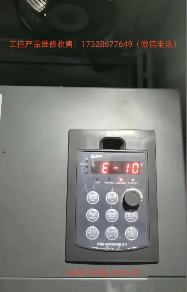
The E10 fault typically indicates an overload of the inverter. When an overload fault occurs, users should first check if the load is too heavy or if the motor is stalled. If the load is normal, try increasing the inverter’s acceleration and deceleration times to reduce the impact on the motor.
2. Maintenance Handling
If on-site handling fails to resolve the issue, it may be necessary to disassemble the inverter for maintenance. During the maintenance process, focus on the following aspects:
- Motor and Load: Confirm whether the motor and load are normal and free from mechanical faults or obstructions.
- Inverter Parameters: Check whether the inverter’s overload protection parameters (such as P9-00, P9-01) are set reasonably.
- Hardware Faults: If the parameter settings are normal and the load is without abnormality, it may be a hardware fault within the inverter, such as damaged power devices or poor heat dissipation. At this point, professional maintenance personnel should be sought for assistance.
Conclusion
The Shenzhen SHZHD Inverter V680 series is a powerful and flexible inverter product. Through this guide, users can better understand the inverter’s operation panel functions, parameter setting methods, the application of torque control and vector control, and common fault handling methods. In practical applications, users should configure parameters and control modes based on specific needs and load conditions to ensure stable operation and high performance of the inverter.
