I. Implementation of Servo JOG Jogging Operation
Implementation Process
Servo JOG (Jogging) operation allows users to manually control the servo motor for short, small movements, primarily used for debugging or precise positioning. The following are the specific steps to implement servo JOG operation:

1. Hardware Connection
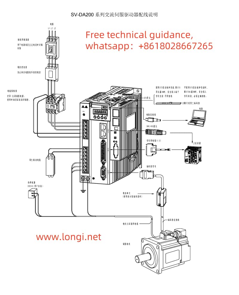
- Connect the Servo Motor: Ensure the servo motor is properly connected to the servo drive, and check that all connecting cables are secure.
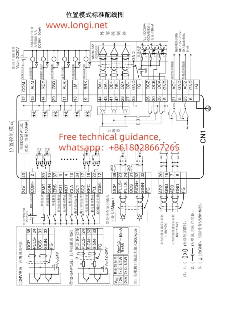
- Control Signal Wiring: According to the CN1 terminal wiring diagram for the DA200 series servo drive, connect the control signal wires to the corresponding CN1 terminals on the servo drive. For JOG operation, typically, servo enable (SON), direction control (e.g., POT, NOT), and jog signal lines need to be connected.
2. Parameter Settings
- Set the Motor Model: Use parameter P0.001 to set the correct motor model to ensure the drive can recognize the connected motor.
- Configure JOG-related Parameters:
- Jogging Speed: Set the jogging speed through parameter P0.05, typically in units of r/min.
- Digital Input Configuration: In the P3.xx series of parameters, configure the digital input functions for servo enable (SON), forward jog (e.g., FJOG), reverse jog (e.g., RJOG), and other related inputs as needed.
3. Software Operation
- Enable the Servo: Activate the servo drive by providing a valid signal to the servo enable terminal (SON).
- Execute JOG Operation: Apply a forward jog (FJOG) or reverse jog (RJOG) signal, and the servo motor will move at the set jogging speed. Control the duration of the jog signal to manage the motor’s movement distance.
Precautions
- Ensure safety during JOG operations to prevent accidental movements that could cause harm.
- Check all connecting cables and parameter settings to ensure correct operation.

II. Servo Positioning via External Pulses in Position Control Mode
Implementation Process
In position control mode, precise servo positioning through external pulse signals is a common application. The following are the implementation steps:
1. Hardware Connection
- Pulse Signal Lines: Connect the pulse signal lines to the pulse input terminals on the servo drive (e.g., PULS+, PULS- on CN1). Depending on requirements, direction signal lines (SIGN+, SIGN-) may also need to be connected.
- Encoder Feedback Lines (if required): If encoder feedback is used, connect the encoder cables correctly to the corresponding terminals on the servo drive.
2. Parameter Settings
- Control Mode Selection: Set parameter P0.03 to 0 for position control mode.
- Pulse Input Configuration:
- Configure the pulse input form (e.g., differential input or open-collector output) and direction signal settings.
- Set the electronic gear ratio (e.g., P0.25, P0.26) to convert external pulses into actual motor shaft movements.
- Position Control-related Parameters:
- Adjust position loop gains (e.g., P2.02) and other control parameters as needed.
- Configure software limits (e.g., P0.35, P0.36) to prevent exceeding safe travel ranges.
3. Software Operation
- Send Pulse Signals: Transmit pulse signals to the servo drive via an upper computer, PLC, or other control system. The number of pulses determines the motor’s movement distance, while the pulse frequency controls the motor’s speed.
- Monitor Status: Use the servo drive’s display panel or upper computer software to monitor the servo motor’s actual position and speed.
Precautions
- Ensure pulse signal quality and stability to prevent positioning inaccuracies due to signal interference.
- Adjust control parameters according to actual needs to achieve optimal control performance.
III. Fault Code Meanings and Solutions
Common Fault Codes and Solutions
- Er10-4: Emergency Stop
- Meaning: The emergency stop signal is active.
- Solution: Check if the emergency stop button or related input signal lines have been triggered accidentally, clear the fault, and re-enable the servo.
- Er22-0: Position Deviation Fault
- Meaning: The actual position deviates significantly from the command position.
- Solution: Inspect the mechanical transmission components for jams or loose connections, adjust position loop gains and other control parameters as needed.
- Er25-1: Overcurrent Fault
- Meaning: The motor current exceeds the rated value.
- Solution: Check if the motor is overloaded, adjust speed or torque loop gains, and ensure the power supply voltage is stable.
- Er13-1: Undervoltage Fault
- Meaning: The main circuit supply voltage is too low.
- Solution: Verify the power supply voltage, troubleshoot line faults, or adjust the power supply voltage.
Precautions
- When encountering fault codes, first consult the fault code table for specific meanings and then follow the corresponding solutions for troubleshooting.
- If faults cannot be resolved, promptly contact technical support or professional maintenance personnel for assistance.
By following the steps and precautions outlined above, users can effectively implement INVT Servo DA200 series JOG jogging operation, position control using external pulses, and fault diagnosis and resolution.
