Posted on Leave a comment

Global Variable Frequency Drive (VFD) repair center

“Longi Electromechanical” has more than 20 years of experience in industrial control maintenance, and is one of the earliest companies engaged in VFD repair. Equipped with artificial intelligence AI maintenance instruments, it specializes in emergency repair of various equipment, with high technical efficiency. It has repaired more than 200,000 units of equipment, including ultrasonic, robot, charging pile, inverter,Variable Frequency Drive (VFD), touch screen, servo, intelligent instrument, industrial control machine, PLC and other products. General problems can be repaired on the same day. LONGI promises you that “if it can’t be repaired, we won’t charge you”. And it provides lifelong maintenance service and free technical consultation for inspection! For urgent repair consultation, please call the contact number or add WHATSAPP maintenance hotline: +8618028667265 Mr. Guo

From European and American brands to Japanese, Korean, and Taiwanese ones, until various domestic brands, we have repaired countless models and specifications of VFDs. In the process of serving our customers, we have continuously learned and accumulated maintenance experience to enhance our skills. We specialize not only in repairing VFDs but also in summarizing various maintenance experiences, elevating them to a theoretical level. We have published the book “VFD Maintenance Technology” and offered VFD maintenance training, thereby promoting the development of the VFD maintenance industry. Longi Electromechanical Company has repaired VFDs from the following brands:

European and American Brands

ABB drives, SEW drives, LUST VFD, LENZE VSD, Schneider drives, CT drives, KEB VSD, Siemens drives, Eurotherm VFD, G.E. VFD, VACON VSD, Danfoss VFD, SIEI VFD, AB VFD, Emerson VFD, ROBICON VFD, Ansaldo VFD, Bosch Rexroth VSD, etc.

Japanese Brands:

Fuji INVERTER, Mitsubishi INVERTER, Yaskawa INVERTER, Omron INVERTER, Panasonic INVERTER, Toshiba INVERTER, Sumner INVERTER, Tooka INVERTER, Higashikawa INVERTER, Sanken INVERTER, Kasia INVERTER, Toyo INVERTER, Hitachi INVERTER, Meidensha INVERTER, etc.

Taiwanese Brands:

Oulin INVERTER, Delta INVERTER, Taian INVERTER, Teco INVERTER, Powtran INVERTER, Dongling INVERTER, Lijia INVERTER, Ningmao INVERTER, Sanji INVERTER, Hongquan INVERTER, Dongli INVERTER, Kaichi INVERTER, Shenghua INVERTER, Adlee INVERTER, Shihlin INVERTER, Teco INVERTER, Sanchuan INVERTER, Dongweiting INVERTER, Fuhua INVERTER, Taian INVERTER (note: Taian is repeated, possibly a mistake in the original list), Longxing INVERTER, Jiudesongyi INVERTER, Tend INVERTER, Chuangjie INVERTER, etc.

Chinese Mainland brands:

Senlan Inverter, Jialing Inverter, Yineng Inverter, Hailipu Inverter, Haili Inverter, Lebang Inverter, Xinnuo Inverter, Kemron Inverter, Alpha Inverter, Rifeng Inverter, Shidai Inverter, Bost Inverter, Gaobang Inverter, Kaituo Inverter, Sinus Inverter, Sepaxin Inverter, Huifeng Inverter, Saipu Inverter, Weier Inverter, Huawei Inverter, Ansheng Inverter, Anbangxin Inverter, Jiaxin Inverter, Ripu Inverter, Chint Inverter, Delixi Inverter, Sifang Inverter, Geli Te Inverter, Kangwo Inverter, Jina Inverter, Richuan Inverter, Weikeda Inverter, Oura Inverter, Sanjing Inverter, Jintian Inverter, Xilin Inverter, Delixi Inverter, Yingweiteng Inverter, Chunri Inverter, Xinjie, Kemron-Bong Inverter, Nihonye Inverter, Edison Inverter

Other brands:
Migao VFD, Rongqi VFD, Kaiqi VFD, Shiyunjie VFD, Huichuan VFD, Yuzhang VFD, Tianchong VFD, Rongshang Tongda VFD, LG VFD, Hyundai VFD, Daewoo VFD, Samsung VFD, etc.

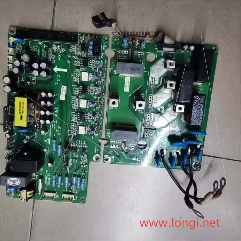
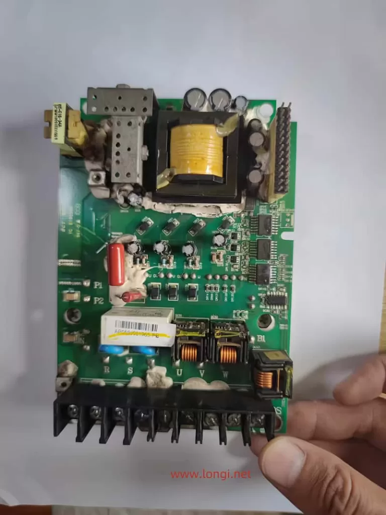
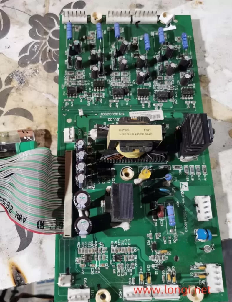
Longi Electromechanical Company specializes in the maintenance of VFDs and strictly requires its engineers to followlow standard operating procedures. Upon receiving a unit, the engineers carefully inspect its exterior and clarify any fault conditions with the customer before beginning work. Any removed circuit boards are cleaned using ultrasonic cleaning equipment. Repaired circuit boards are coated with high-temperature and high-pressure-resistant insulating paint, dried in a drying machine, and then reinstalled in the VFD, with measures taken to prevent corrosion and interference.
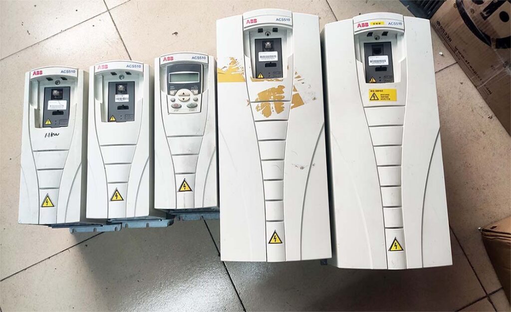
The repaired VFD will undergo a simulated operation with load using a heavy-load test bench to avoid any potential issues that may arise under actual load conditions on site.

When it comes to VFD maintenance, most cases are related to the equipment on site. Sometimes a standalone unit may have been repaired, but it doesn’t work properly when installed on site. In some cases, the problem lies with the system rather than the VFD itself. For such issues, if the customer requests on-site service, we will do our utmost to resolve the problem for them. If the location is far away, such as in another province, we can use tools like video conferencing and phone calls to allow our engineers to remotely diagnose and resolve the on-site issues for the customer.

Posted on Leave a comment

Three Examples of IGBT Module and Driver Fault Frequency Converter Maintenance Process

A. One Dongyuan 7300PA3.7kW frequency converter was sent for repair. The power was connected and it was detected that there was output in the U, V, and W phases, but there was severe phase deviation. It was determined that the drive circuit was abnormal or the module was damaged. Measure the open circuit of the upper arm diode inside the U-phase power stage of the inverter circuit. In general, the IGBT transistor connected in parallel with this diode is also often damaged. In fact, the IGBT tubes were first burnt out by short-circuit current, and the parallel diodes were also damaged by the impact.

After removing the inverter module SPIi12E, all the pins of the inverter module are empty, and the six drive circuits are ready to be tested when powered on. Once powered on, the frequency converter experiences an overheating fault, and the CPU locks the output of the drive pulse in the fault state. Due to the absence of trigger pulse output, it is impossible to detect the quality of the driving circuit. The locking state of the overheating fault must be temporarily released before checking the quality of the drive circuit.
Observe that the inverter module on the circuit board has two terminals labeled T1 and T2, which may be the internal overheat alarm output terminals of the module. One end is led into a 5V power supply through a resistor, and the other end is grounded. When this terminal is suspended, T1 terminal outputs a high-level module overheating signal through an pull-up resistor to protect the shutdown. After short circuiting the T1 and T2 terminals, there will be no protective shutdown when power is supplied.
Check that there is no trigger pulse output in the IGBT drive circuit of the U-phase upper arm. After replacing the drive circuit IC/PC923, the six pulse outputs are normal.
After replacing the IGTB inverter module with a new one, remove the short circuit of the T1 and T2 terminals, and conduct a power test to ensure normal operation. Experience has shown that when an IGBT tube is damaged, the corresponding drive IC will also be damaged due to impact. It is also necessary to inspect the drive IC of the same branch of the damaged module and not hastily replace it with a new module to avoid causing damage to the new module again due to abnormal drive circuit!
B. An Alpha 18.5kW frequency converter with six single tube IGBT tubes (modules) forming a three-phase output circuit, one of which is damaged. CPU motherboard jumps 2501, panel operation fails. The cause of the malfunction of the machine was damage caused by lightning strikes.

The operation panel shows 2501 when powered on, and all operations are malfunctioning. CPU motherboard malfunction, caused by damage to the CPU and peripheral communication circuits. Let’s not worry about it for now. First, fix the driver board before proceeding.
Check the driving circuit, a total of six A316J chips are responsible for six driving pulse output tasks. Three drive circuits that output upper arm pulses are damaged, but there are no integrated circuits of the same model available for replacement. Based on the experience of repairing other brands of frequency converters, using only three A316J chips (used for three-phase lower arm drive) as the three-phase OC signal alarm output can meet the protection requirements. Therefore, the other three pieces were replaced with 3120 (same as PL250V) to drive the optocoupler IC. The original IC was packaged in a 16 pin dual row SMT package, and the replaced IC was packaged in an 8-pin dual row inline package. But the connection is also relatively convenient. Only weld the 8 pins of the new IC to the original 12/13 pins, weld the 5 pins of the new IC to the original 9/10 pins, and connect the 6/7 pins of the new IC to the original 11 pins; Due to the original IC input method being an operational amplifier input and the new IC being a photoelectric tube input, a larger input current is required. Remove the 202 grounding resistor from the original input side and replace it with a 5.1k resistor. Connect the 3 pins of the new IC to ground, and connect the original 1 pin in series with a 300 ohm resistor to the 2 pins of the new IC. Power on and test, and the static voltage is normal.
At this point, after replacing the CPU motherboard with a new one, the static output negative pressure and dynamic pulse output of the six drive circuits were tested to be normal upon power on. After replacing the damaged IGBT module, the machine was tested normally.

C. A 7.5kW frequency converter has been reported by the user as having no major issues, but it has output but cannot operate due to phase deviation. Check if there is an abnormality in one of the six driving circuits. The driving IC model is PC929 (or A4503?). Measure that there are no pulse outputs on the input and output sides of the driving IC. The input side of the IC is directly connected to the pulse output terminal of the CPU. Suspecting a faulty internal pin circuit of the CPU, the PC929 input terminal was disconnected. The voltage at the CPU pulse output terminal increased, but as soon as the driver IC was connected, it dropped to nearly 0V.
Analysis: Due to the direct output of the CPU driving the photoelectric tube, it needs to output a large current. Long term operation may cause aging and failure of the output stage or other faults, resulting in an increase in output internal resistance. When unloaded, there is a certain amplitude of voltage signal, but once connected to the load, even if the signal voltage drops significantly. Replacing the CPU motherboard for this malfunction is a quick solution. One reason is that the maintenance cost is high, and the other reason is that it still needs to be purchased externally, and the repair time required by the user is very tight. Isn’t there a better way? Based on the above analysis, although the pulse output pin of the CPU has aging and failure phenomena, which greatly reduces its load capacity, assuming that its signal current is not used and only its output voltage signal is used, this defect can still be remedied to achieve the purpose of repair. By passing the CPU pin through an external amplifier stage, the signal voltage should meet the requirements for driving the photodiode (PC929 input side photodiode).
Measure that both pins on the input side are 5V high level, and the pin connected to the CPU is a negative pulse input. If you have a PNP transistor on hand, connecting one transistor and a 5k resistor should be able to complete the task. But I only have NPN type transistors on hand, which can only be achieved by using two inverters. Disconnect one pin of the driver IC from the CPU output, connect the copper foil strip to a 50k resistor, and then connect the base of the transistor. Connect the collector in series to the base of the next transistor, and then connect it to+15V through a 10k resistor. Ground the two emitters and connect the lower collector to the disconnect pin of the driver IC. Power on test machine, six pulse outputs are normal. Restore the power supply to the inverter module, and the three-phase voltage output is normal.
The CPU of this machine is damaged and faulty. After using two resistors and two transistors, the problem was resolved and successfully repaired.

Posted on Leave a comment

Repair process of TECO 7200GA-22kW VSD after lightning strike

Received a 7200GA-41kVA frequency converter for repair, which is a lightning fault. After replacing the damaged input rectifier module, switch tube, and shunt tube of the switching power supply, the operation panel screen displayed normally, indicating that the problem is not significant.

The negative pressure and optocoupler drive input signals of the six channels were tested to be “normal”. During the assembly test of the whole machine, the OC jumped immediately upon power on, but the operation could be started after resetting. The screen frequency output was normal, but there was no three-phase voltage output at the U, V, and W terminals during the actual test. The local driving IC adopts optocouplers PC923 and PC929, which cooperate with SN0357 to return OC signals.
Check the power amplifier circuit on the output side of the driving IC and the detection circuit of the IGBT tube, and there are no abnormalities. When testing the pulse input pin of PC923, it doesn’t feel right. Why is the level of pin 3 high and pin 2 low? Is it because the driver power supply is reversed? 2. Three pins are the input circuit of the photodiode, two pins are the anode of the photodiode, and three pins are the cathode of the photodiode. According to common sense, the two pins are usually powered by+5V and then stabilized to provide an excitation power of about 4V, while the three pins are connected to the pulse output terminal of the CPU. Low level output is effective, that is, when outputting, current is pulled in from the three pins of PC923 to make the diode conductive. When there is a trigger pulse input and the frequency is low, the voltage of pin 3 oscillates up and down to 3V. As the frequency increases, the voltage of pin 3 gradually stabilizes at around 3V. When there is no output, pin 3 is a high level of around 4V (equal to the level value of pin 2).
The current detection results are as follows: when no running command is input, pin 3 is a high level of 0.5V, and pin 2 is a low level close to 0V; When entering the run command, pin 3 drops to 0.2V and there is a change in high and low levels, indicating that the CPU pulse has reached PC923. At the beginning of the maintenance, I took a detour and only paid attention to the changes in high and low levels, without paying attention to the magnitude of the voltage value. Obviously, the loss of 2-pin power supply voltage prevents the IGBT transistor from receiving excitation pulses, resulting in no output voltage from the frequency converter.
Check that the 2-pin power supply is a simple series connected voltage regulator with a transistor and a voltage regulator. The base bias resistance of the transistor is open, causing the supply voltage to be zero. After replacing the bias resistor, measure the voltage on pins 2 and 3 of PC923 to return to normal. After receiving the operation command, the frequency converter has output from the U, V, and W terminals.
Further investigate the reason for the OC jump upon power on. Measure the SN0357 optocoupler device that transmits the OC signal, and the voltage value of the two pins on the input side is zero, indicating that it did not input the OC signal. However, measure the voltage value of the two pins on the output side of the three optocouplers to be 0.5V! But since there is no OC signal input, the voltage between the two pins should be 5V (one pin is connected to a 5V ground level), and there is only one possibility, that is, the 5V pull-up resistance of the signal output pin has changed or is open circuit. At this point, the CPU mistakenly believes that it has received the OC signal returned by the drive circuit, and therefore gives an alarm. Try connecting a 10k resistor between the signal output pin and the 5V power supply. Start up and test the signal output pin to be 5V. Repeat the power supply several times and no longer experience OC faults.

The above two faults actually come from one reason: power loss. The input pin of the pulse signal and the output pin of the OC signal are both directly connected to the CPU pin. When the pull-up high level disappears, the CPU pin only has a low level of 0.5V left. This level is not enough to drive the optocoupler to send out the trigger signal of the inverter module, and it also leads to the detection of low levels and the jumping of the OC fault code when powered on. And 0.5V is also the critical level for detecting signals such as OC, so after performing a reset operation, it can start running again.
Note:
The motherboards of various series of Dongyuan frequency converters have good replacement characteristics, and after replacement, only the corresponding capacity value of the frequency converter needs to be readjusted. After changing its capacity value, the relevant parameters for checking the rated current value of the motor are also automatically modified.
The capacity labeling of Dongyuan frequency converters is mostly not based on kW, but on kVA. For example, for a 22kW capacity, it is labeled as 41kVA with a rated current of around 48A. In the relevant manual, the capacity is set by comparing the HP horsepower with the rated current. Moreover, the setting of horsepower size is not simply expressed in numerical terms, but also mixed with English letters to indicate the size of horsepower value (actually using hexadecimal notation). When initially adjusting its capacity value, it is often difficult for Master Zhang Er to understand and adjust it, and the parameters cannot be written in.
The corresponding relationship between kW, KVA, and HP values is not clear to most users. I don’t know what the Dongyuan people were thinking about doing this. 1HP=0.75kW, indicating that the horsepower is less than the kW value; KW is the active power value, which can be approximated as the actual power value. That is, a 22kW frequency converter can drive a 22kW motor, and the power capacity is sufficient; And kVA is the apparent power value, which means that when there is such power, but it drives some loads such as motors/inductive loads, it cannot reach the marked output value because the motor load requires reactive power consumption, and kVA is the sum of active power and reactive power. The kVA value is virtual (not discussed here) and can be selected based on the rated current value.

The comparison table between the motor capacity HP and the set value is as follows:
HP: Set value:
25 (18.5kW) 29
30 (22kW) 2A
40 (30kW) 2B
50 (37kW) 2C
60 (45kW) 2D
75 (55kW) 2E
100 (75kW) 2F
125 (90kW) 30
150 (110kW) 31
175 (130kW) 32
215 (160kW) 33