Posted on Leave a comment

Comprehensive Analysis of Headspace Sampler: Principles,Brand, Usage Methods, and Troubleshooting Guide

I. Overview of Headspace Sampler

The headspace sampler is an efficient and convenient sample pretreatment method in gas chromatography. Its principle involves placing the sample to be tested in a sealed container, heating it to volatilize the volatile components, achieving equilibrium in the gas-liquid (or gas-solid) phases, and then directly extracting the top gas for chromatographic analysis to detect the composition and content of volatile components in the sample. This technique simplifies the sample pretreatment process, avoids the interference of organic solvents, and reduces contamination of the chromatographic column and injection port.

II. Principles of Headspace Sampler

The working principles of the headspace sampler are mainly divided into two types: solution headspace and solid headspace.

  • Solution Headspace: The sample is dissolved in an appropriate solvent and placed in a headspace vial, which is then heated for a certain period to allow the residual solvent to reach equilibrium in the gas-liquid phases. Subsequently, a quantitative amount of gas is sampled for measurement.
  • Solid Headspace: The solid sample is directly placed in the headspace vial and heated for a certain period to allow the volatile components to reach equilibrium in the gas-solid phases. Afterwards, a quantitative amount of gas is sampled for measurement.

III. Usage Methods

Preparation Stage:

  1. Accurately transfer the sample to the headspace vial and seal it.
  2. Place the headspace vial in the heating oven and allow it to equilibrate for the preset time.

Parameter Setting:

  1. Set parameters such as heating temperature of the headspace vial, temperature of the quantitative tube, and temperature of the transfer line as needed.
  2. Ensure that the headspace sampler is correctly connected to the gas chromatograph, and set the appropriate carrier gas flow rate and split ratio.

Sampling Operation:

  1. Use the pressure method or equilibrium method to introduce the headspace gas into the gas chromatograph.
  2. After starting the sampling, wait for the sample peak to finish, press the cleaning button to clean, and then proceed with the next sample.

Data Analysis:

  1. Analyze the data obtained from the gas chromatograph to calculate the composition and content of volatile components in the sample.

IV. Common Faults and Repair Methods

Unable to Sample Normally:

  • Fault Causes: Insufficient pressure, valve failure, sealing issues, clogged sampling needle.
  • Repair Methods: Check the gas source pressure, clean or replace the valve, replace sealing components, clean the sampling needle, and ensure it is dry before reinstallation.

Gas Leakage:

  • Fault Causes: Loose connections or aged sealing components.
  • Repair Methods: Check the tightness of connections, replace aged or damaged sealing components, and apply sealing glue if necessary to enhance sealing.

Inaccurate Sampling Volume:

  • Fault Causes: Clogged sampling needle, stuck or leaky valve.
  • Repair Methods: Regularly clean the sampling needle, calibrate the sampling volume, and inspect and address valve faults.

Slow Sampling Speed:

  • Fault Causes: Insufficient gas source pressure, clogged sampling needle, stuck valve.
  • Repair Methods: Check and repair the gas source pressure issue, clean the sampling needle, and address the stuck valve problem.

Other Mechanical Faults:

  • For mechanical faults such as rusted lifting rods, follow the equipment manual or disassembly videos provided by technical support to disassemble, remove rust, lubricate, and reinstall.

V. Conclusion

As an important tool in gas chromatographic analysis, the headspace sampler is widely used in various fields due to its efficiency and convenience. Correctly understanding and operating the headspace sampler, as well as promptly addressing common faults, are crucial for ensuring the accuracy and efficiency of experimental results. This article summarizes the basic principles, usage methods, and common fault repair methods of the headspace sampler, aiming to provide comprehensive reference and guidance for users.

VI. Brands and Models of Headspace Samplers Repaired by Longi Electromechanical Company

  1. Agilent Technologies
    • 7697A: Headspace Sampler
    • 7650A: Automatic Headspace Sampler
    • 7694E: Headspace Sampler
  2. PerkinElmer
    • TurboMatrix Series: TurboMatrix 40, TurboMatrix 110, TurboMatrix 16, TurboMatrix 650 ATD, TurboMatrix 350 ATD
  3. Thermo Fisher Scientific
    • TriPlus Series: TriPlus 300 HS, TriPlus 500 HS, TriPlus 100 LS
  4. Shimadzu
    • HS-20 Series: HS-20, HS-10
  5. GERSTEL
    • MultiPurpose Sampler (MPS): Integrates headspace, solid-phase microextraction (SPME), and other multifunctional sampling
    • Dual Headspace Sampler: Efficient multi-sample sampling
  6. CTC Analytics (PAL System)
    • PAL RSI: Robotic Sample Injector with headspace option
    • PAL RTC: Robotic Tool Change system with headspace option
  7. Teledyne Tekmar
    • HT3: Headspace Autosampler
    • Versa: Automated Headspace Vial Sampler
  8. LECO Corporation
    • PEGASUS HT-C: Headspace Sampler
    • HTS: High Throughput Sampler
  9. Markes International
    • CIA Advantage: High-capacity headspace autosampler
  10. EST Analytical
    • Evolution: Automated Headspace Sampler
  11. OI Analytical (Xylem)
    • 4560: Purge-and-Trap Sample Concentrator with headspace option
  12. Alpha MOS
    • HS100: Headspace Autosampler
  13. Dani Instruments
    • Master DHS: Dynamic Headspace Sampler
    • Master SHS: Static Headspace Sampler
  14. Entech Instruments
    • 7100A: Preconcentrator with headspace option
  15. Horizon Technology
    • SmartPrep: Automated Extraction System with headspace option

Longi Electromechanical Company has nearly 30 years of experience in repairing headspace samplers and can quickly repair various instruments. Additionally, the company recycles and sells various headspace samplers. Welcome to consult.

Posted on Leave a comment

Comprehensive Analysis of Coordinate Measuring Machine (CMM): Principles,Usage,Brand,Troubleshooting, and Maintenance Guide

1. Principles

The Coordinate Measuring Machine (CMM) operates on the principle of three-point positioning within a three-dimensional coordinate system. Equipped with a detector capable of moving in three directions along mutually perpendicular guides, it captures coordinate information of points on the surface of the object being measured, either through contact or non-contact methods. By scanning the object’s surface, the detector records the three-dimensional coordinates of various points. These coordinates are then processed by a computer to fit measurement elements such as points, lines, planes, and circles, and to calculate the geometric dimensions, shape, and positional errors of the object.

2. Usage

Preparation:

  • Ensure the CMM is level and free from surrounding interferences.
  • Select appropriate detectors and fixtures; prepare the part to be measured.

Installation and Calibration:

  • Install the part on the CMM and secure it with fixtures, aligning it with the machine’s coordinate axes.
  • Perform probe calibration, selecting suitable probes and styli, and calibrate to achieve the required measurement accuracy.

Establishing Coordinates:

  • Based on the part’s shape and size, establish a workpiece coordinate system. If a workpiece model is available, establish a model coordinate system and fit the two.

Measurement:

  • Choose appropriate measurement methods (e.g., point, line, circle, surface measurements) according to the part’s characteristics.
  • Conduct precise measurements and export the data for analysis, assessing the part’s accuracy and deviations.

3. Common Faults and Repair Methods

  • Large Measurement Errors:
    • Causes: Low surface roughness of the workpiece, contaminated measuring head, unstable measurement environment (temperature, humidity fluctuations).
    • Solutions: Improve surface roughness, clean the measuring head, maintain a stable measurement environment.
  • Unable to Start:
    • Causes: Power supply issues, equipment failure.
    • Solutions: Check power connections and replace if necessary; contact the manufacturer for repairs if equipment failure.
  • Slow Operation:
    • Causes: Equipment aging, software issues.
    • Solutions: Replace with new equipment or update/reinstall software.
  • Inaccurate Measurements:
    • Causes: Improper adjustment of the measuring head, equipment failure.
    • Solutions: Readjust the measuring head for accuracy; contact a repair service if equipment failure.
  • Loss of Coordinate Zero Point:
    • Causes: Computer software issues.
    • Solutions: Reload backup software and restart the machine.
  • Abnormal Coordinate Axis Movement:
    • Causes: Insufficient air bearing pressure, blocked air holes, loose or slipping transmission components.
    • Solutions: Check the air supply system for proper pressure, clean air bearing holes, tighten and adjust transmission components.
  • Probe Automatic Changer Malfunction:
    • Causes: Related power or control component failures.
    • Solutions: Inspect and repair related power or control components.

4. Brands and Models Repaired by Longi Electromechanical

  • Hexagon Metrology:
    • Leitz Reference HP: High-precision CMM.
    • Global S: Universal CMM.
    • Optiv Performance: Multi-sensor CMM.
    • DEA Alpha 2.0: Large bridge-type CMM.
    • TIGO SF: Compact workshop CMM.
  • Zeiss:
    • PRISMO: High-precision CMM.
    • CONTURA: Universal CMM.
    • ACCURA: Configurable CMM.
    • MICURA: Small high-precision CMM.
    • DuraMax: Compact workshop CMM.
  • Mitutoyo:
    • CRYSTA-Apex S: High-precision CMM.
    • CRYSTA-Apex V: Universal CMM.
    • Legex 574: Ultra-high-precision CMM.
    • Strato-Apex 574: Ultra-high-precision CMM.
    • Quick Vision: Multi-sensor measurement system.
  • Nikon Metrology:
    • Altera: Universal CMM.
    • Innova: High-precision CMM.
    • H ALTERA: High-precision bridge-type CMM.
    • LK V: High-performance bridge-type CMM.
    • NEXIV VMZ-R: Video measurement system.
  • Wenzel:
    • LH Series: LH 65, LH 87, LH 1210.
    • XCite: Economical CMM.
    • XO: High-performance CMM.
    • SF 87: High-speed scanning CMM.
  • FARO:
    • FARO Edge: Portable CMM arm.
    • FARO Gage: Compact measuring arm.
    • FARO Quantum: High-precision measuring arm.
    • FARO Vantage: Laser tracker.
  • Brown & Sharpe (Hexagon):
    • GLOBAL Silver: High-performance CMM.
    • ONE: Universal CMM.
    • MICRO-HITE: High-precision measuring instrument.
  • Aberlink:
    • Axiom Too: High-precision CMM.
    • Zenith 3: High-performance CMM.
    • Extol: Economical CMM.
  • Carl Zeiss Industrial Metrology:
    • XENOS: Ultra-high-precision CMM.
    • MMZ G: Large CMM.
    • ACURA: Multi-functional CMM.
  • LK Metrology:
    • Altera M: Universal CMM.
    • Altera S: High-performance CMM.
    • C10: Large bridge-type CMM.
  • Hikrobot:
    • HS Series: HS5030, HS5040, HS5050, HS5060, HS5070.
    • HT Series: HT5030, HT5040, HT5050, HT5060, HT5070.
    • HL Series: HL5030, HL5040, HL5050, HL5060, HL5070.
    • HME Series: High-precision CMM, HME5030, HME5040, HME5050.

Longi Electromechanical has nearly 30 years of experience in repairing CMMs, ensuring quick and efficient repairs. Additionally, we offer the sale and purchase of various used CMMs. Please feel free to contact us for more information.

Posted on Leave a comment

Cause Analysis and Solution for FF89 Alarm on ABB VFD ACS800

The ABB ACS800 VFD (Variable Frequency Drive) plays a pivotal role in industrial automation, finding extensive applications across various industrial control systems. However, during operation, it may encounter various alarm messages.

ACS800 VFD panel display fault

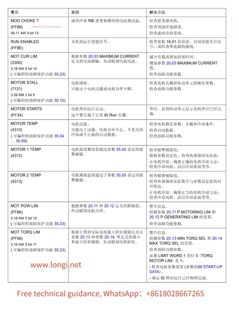
Alarm Message: FF89 – MOD CHOKE T (FF89) 09.11 AW 3 bit 13

Cause:

  • Overheating of Reactor in Liquid-Cooled R8i Inverter Module
    The reactor in the liquid-cooled R8i inverter module has exceeded its temperature threshold.

Resolution Steps:

  1. Check the Inverter Fan:
    • Ensure the inverter fan is operating properly and providing sufficient cooling to the reactor.
    • Inspect for any blockages or dirt accumulation that may impede airflow.
  2. Inspect Ambient Temperature:
    • Verify that the ambient temperature surrounding the VFD is within the recommended range.
    • Ensure there are no heat sources in close proximity that could contribute to overheating.
  3. Examine the Liquid Cooling System:
    • Thoroughly check the condition of the liquid cooling system, including pipes, pumps, and radiators.
    • Confirm that the coolant flow rate and temperature are within normal operating parameters.
    • Inspect for leaks or corrosion that could indicate a need for maintenance or replacement.
  4. Review VFD Operation and Configuration:
    • Ensure the VFD is not operating under excessive load conditions that could lead to overheating.
    • Check the VFD’s settings and parameters to verify they are appropriate for the application and load requirements.
  5. Check for Alarms or Warnings in the VFD’s Diagnostic System:
    • Use the VFD’s diagnostic tools or software (such as DriveWindow) to check for any additional alarms or warnings that may provide further insight into the issue.
  6. Service and Maintenance:
    • If the above steps do not resolve the issue, consider scheduling preventive maintenance or contacting ABB support for further assistance.
ACS800 Fault Code Table

By following these resolution steps, you can effectively diagnose and address the FF89 alarm on your ABB ACS800 VFD, ensuring reliable and efficient operation of your industrial automation system.

Posted on Leave a comment

Operation, Brand,Maintenance, and Troubleshooting of Centrifuges: A Comprehensive Guide

Introduction

A centrifuge is a device that utilizes centrifugal force to separate different components in a mixture. Its working principle is based on Newton’s second law, where the centrifugal force experienced by an object during rotation is proportional to the square of the angular velocity and the radius of rotation, and also proportional to the mass of the object. In a centrifuge, substances are placed on a rotating turntable and accelerated along with it. As the rotation speed increases, the substances experience centrifugal force, leading to their separation into different components. Factors such as the rotation speed, turntable diameter, and turntable material of the centrifuge all influence the magnitude of the centrifugal force and the effectiveness of the separation.

I. Operation Method of the Centrifuge

The operation of a centrifuge generally involves the following steps:

Preparation Stage:

  • Check if the centrifuge is in normal working condition.
  • Prepare necessary centrifuge tubes, turntables, and other accessories.

Loading Samples:

  • Place the substances to be separated into centrifuge tubes.
  • Position the centrifuge tubes on the turntable of the centrifuge, ensuring they are correctly placed and evenly distributed to maintain balance.

Setting Parameters:

  • Set the parameters of the centrifuge, such as rotation speed and centrifugation time, according to the separation requirements and sample characteristics.

Starting the Centrifuge:

  • Press the start button to initiate the centrifuge.

Monitoring the Centrifuge:

  • Monitor the running status of the centrifuge during operation to ensure the centrifugation process proceeds normally.

Stopping the Centrifuge:

  • After centrifugation is complete, press the stop button, halt the centrifuge, and retrieve the separated substances.

II. Common Faults and Troubleshooting Methods for the Centrifuge

The centrifuge may encounter various faults during use. Below are some common faults and their troubleshooting methods:

  • Unbalanced Centrifuge or Uneven Placement of Centrifuge Tubes:
    • Adjust the level of the centrifuge to ensure it is stable.
    • Evenly distribute the centrifuge tubes to avoid imbalance caused by uneven weight distribution.
  • Loose or Damaged Rotor:
    • Check if the rotor is loose or damaged, and replace it if necessary.
  • Loose Screws, Worn Bearings, or Motor Faults:
    • Tighten the screws of the centrifuge.
    • Check for bearing wear and replace if necessary.
    • Check for motor faults and repair or replace if needed.
  • Blocked Oil Filter or Oil Leakage:
    • Inspect the oil filter, oil pipes, and connectors to ensure they are unblocked.
    • Check for oil leakage and repair promptly if found.
  • Power Issues or Damaged Circuit Board:
    • Check if the power plug is properly inserted and the power cord is energized.
    • Check if the fuse is burned out and try replacing it.
    • If the above are normal, the circuit board may be damaged and needs to be returned for repair or replacement.
  • Water Circuit Issues or Damaged Seal Rings:
    • Check if the water circuit is unblocked and the solenoid valve is functioning properly.
    • Inspect the seal rings for damage or impurities and replace if necessary.

III. Maintenance Methods for the Centrifuge

The maintenance of a centrifuge mainly includes the following steps:

  • Cleaning:
    • Regularly clean the centrifuge to remove accumulated dirt and residues, restoring the design dimensions of the cavity.
  • Inspection:
    • Regularly inspect various components of the centrifuge, including feed pipes, drums, spirals, housing, frames, and motors, to ensure they are in normal structure and working condition.
  • Calibration:
    • Regularly calibrate the assembly components of the centrifuge to ensure good dynamic balance.
  • Lubrication:
    • Regularly lubricate the bearings, gears, and other components of the centrifuge to reduce wear and extend service life.
  • Maintenance:
    • Regularly maintain the centrifuge, including replacing worn components and cleaning internal dirt.
  • Fault Diagnosis:
    • Promptly diagnose the cause of any faults in the centrifuge through methods such as listening to sounds, checking the power supply, and viewing fault codes on the display. Seek professional assistance if unable to resolve.

IV. Centrifuge Brands and Models Repaired by Longi Electromechanical Company

  1. Beckman Coulter:
    • Avanti JXN-30
    • Avanti JXN-26
    • Allegra X-30 Series
    • Allegra V-15R
    • Microfuge 20 Series
    • Optima XE/XPN Series (XE/XPN-90, XE/XPN-100, XE/XPN-80)
  2. Thermo Fisher Scientific:
    • Sorvall LYNX 6000
    • Sorvall Legend X1/X1R
    • Sorvall ST 16/ST 16R
    • Sorvall RC 6 Plus
    • Sorvall Evolution RC
    • Sorvall BIOS 16
    • Sorvall WX+ Ultracentrifuge Series (WX Ultra 80, WX Ultra 90, WX Ultra 100)
  3. Eppendorf:
    • 5810/5810 R
    • 5910/5910 R
    • 5424/5424 R
    • 5430/5430 R
    • 5804/5804 R
    • Centrifuge 5920 R
    • Centrifuge 5702/5702 R
  4. Hettich:
    • Rotina 420/420R
    • Rotofix 32A
    • Rotina 380/380R
    • Universal 320/320R
    • EBA 200/200S
    • Mikro 200/200R
  5. Sigma:
    • Sigma 8K
    • Sigma 6-16 KS
    • Sigma 3-30KS
    • Sigma 2-16K
    • Sigma 1-14
    • Sigma 4-5L
    • Sigma 3-18KS
  6. Sorvall:
    • Sorvall RC-5B Plus
    • Sorvall RC 12BP Plus
    • Sorvall Legend XTR/X1R
    • Sorvall MTX 150
    • Sorvall RC-6 Plus
  7. Beckman Optima:
    • Optima MAX-XP
    • Optima MAX-TL
    • Optima XPN/XE
  8. Hitachi:
    • Himac CR21GIII
    • Himac CS150FNX
    • Himac CR30NX
  9. HERMLE:
    • Z36HK
    • Z446
    • Z326
    • Z216MK
  10. Thermo Sorvall:
    • Thermo Sorvall LYNX 4000/6000
    • Thermo Sorvall WX 80/90/100 Ultra Series
  11. KENDRO (Acquired by Thermo Fisher):
    • High-Efficiency Centrifuges: Sorvall RC-6 Plus, Sorvall RC-5C Plus, Sorvall RC-3BP Plus
    • Ultrahigh-Speed Centrifuges: WX Ultra 80, WX Ultra 90, WX Ultra 100
    • Benchtop Centrifuges: Heraeus Multifuge X3/X3R, Heraeus Megafuge 8/8R
    • Microcentrifuges: Heraeus Pico 21/Pico 21R, Heraeus Fresco 17/Fresco 17R
    • Multifunctional Centrifuges: Sorvall Legend X1/X1R, Sorvall Legend XT/XTR
  12. Hunan Xiangyi:
    • CH210
    • CHT210R
    • HT150R
    • HT165R
    • HT200
    • HT200R
    • H2050R

Conclusion

Longii Electromechanical Company has nearly 30 years of experience in repairing centrifuges and can quickly repair various instruments. Additionally, we recycle and sell various used centrifuges. Welcome to consult with us.

Posted on Leave a comment

Chromatography Instrument Maintenance Center: Principles, Usage, Brand,and Troubleshooting for Various Chromatographs

I. Introduction to Chromatography Instruments

Chromatography instruments separate and analyze mixtures based on the physicochemical properties of their components. Common types include Gas Chromatographs (GC), Online Gas Chromatographs, Liquid Chromatographs (HPLC/UPLC), Ion Chromatographs, PE Atomic Absorption Spectrometers, and Zeeman Effect Atomic Absorption Spectrometers. The core principle involves the distribution or adsorption equilibrium of substances between the stationary and mobile phases to achieve separation. After vaporization in the vaporization chamber, the sample is carried into the column by an inert gas (carrier gas, such as N2, He, etc.). Due to differences in boiling point, polarity, or adsorption properties, components in the sample exhibit different distribution or adsorption behaviors in the column, leading to varying elution times and thus separation. The separated components enter the detector, which converts the presence of sample components into electrical signals proportional to the quantity or concentration of the measured components.

II. Usage Instructions

Startup Preparation:

  • Turn on the gas generator and observe if the pressure gauges for air, hydrogen, and nitrogen reach the specified positions.
  • Turn on the chromatograph power switch and adjust the temperatures of the injector, column, and detector.

Ignition and Sample Injection:

  • When the temperatures reach the set values, ignite the detector flame and adjust the hydrogen flow rate.
  • After the signal stabilizes, quickly inject the sample from the sampling cylinder into the chromatograph using a syringe, and record the peak shape and test data.

Data Processing:

  • Repeat measurements multiple times and calculate the average to improve accuracy.
  • After the test, extinguish the flame, turn off the injector and detector, and wait for the column temperature to drop to room temperature before turning off the chromatograph power.

III. Common Faults and Troubleshooting

Injector Faults:

  • Blockage: Reinstall the injector plunger and clean with a suitable solvent.
  • Leakage: Check and replace the injector seal if aged.
  • Improper Installation: Ensure the injection needle is correctly installed on the injector plunger.

Column Faults:

  • Blockage: Disconnect the column from the detector end, check for bubbles, and attempt reverse flushing or replacement.
  • Contamination: Cut off the contaminated part of the column and re-age or clean it.
  • Reduced Efficiency: Replace the column or perform aging treatment.

Detector Faults:

  • Abnormal Signal: Check and clean the detector nozzle and gas pipeline regularly.
  • Decreased Sensitivity: Adjust detector sensitivity settings and check gas flow rates.
  • Contamination: Use high-temperature aging or solvent cleaning for the detector.

System Leaks:

  • Check instrument connections, seals, or pipelines for tightness and replace damaged parts.
  • Use leak detection solution to check connection points for leaks and ensure instrument sealing.

Background Noise and Baseline Drift:

  • Check for a stable instrument environment and adjust detector sensitivity and baseline.
  • Regularly calibrate the instrument and check the stability of flow rate, temperature, and pressure parameters.

Flow Rate Issues:

  • Check the injection system, flow controller, and column for stable flow.
  • Replace the gas flow control valve or adjust gas flow settings.

Sample Contamination:

  • Prepare clean samples and regularly clean the injector and system.
  • Use pre-columns or guard columns to capture semi-volatile and non-volatile impurities.

IV. Maintenance Precautions

  • Before any maintenance, always turn off the chromatograph power and disconnect from the power source.
  • Use appropriate tools and solvents for cleaning and maintenance to avoid damaging instrument components.
  • Regularly maintain and service the instrument, such as replacing filters and cleaning nozzles and gas pipelines.
  • For complex faults, consult the instrument operation manual or seek assistance from professional technicians.

V. Brands and Models Repaired by Rongji Electromechanical Company

Agilent Technologies:

  • GC: 8890 GC System, 7890B GC System, 8860 GC System
  • HPLC/UPLC: 1290 Infinity II LC System, 1260 Infinity II LC System, 1220 Infinity II LC System
  • GC-MS: 8890 GC/MSD System, 7250 GC/Q-TOF, 7010 Triple Quadrupole GC/MS
  • LC-MS: 6546 LC/Q-TOF, 6470 LC/TQ, 6495B LC/TQ

Thermo Fisher Scientific:

  • GC: TRACE 1310 GC, TRACE 1300 GC
  • HPLC/UPLC: Vanquish UHPLC System, UltiMate 3000 HPLC System
  • GC-MS: TSQ 9000 GC-MS/MS, ISQ 7000 Single Quadrupole GC-MS
  • LC-MS: Orbitrap Exploris 240, TSQ Altis Triple Quadrupole, Q Exactive HF-X

Shimadzu:

  • GC: Nexis GC-2030, GC-2010 Plus
  • HPLC/UPLC: Nexera X2 UHPLC, Prominence HPLC
  • GC-MS: GCMS-QP2020 NX, GCMS-TQ8050 NX
  • LC-MS: LCMS-8050, LCMS-8060

Waters:

  • HPLC/UPLC: ACQUITY UPLC H-Class PLUS, ACQUITY Arc System, Alliance HPLC System
  • LC-MS: Xevo TQ-S micro, Xevo G2-XS QTof, SYNAPT XS

PerkinElmer:

  • GC: Clarus 690 GC, Clarus 580 GC
  • HPLC/UPLC: Flexar UHPLC, Flexar HPLC, LC-2030C
  • GC-MS: Clarus SQ 8 GC/MS
  • LC-MS: QSight 220 Triple Quad

Bruker:

  • GC-MS: SCION TQ, SCION SQ
  • LC-MS: timsTOF Pro, maXis II

SCIEX:

  • LC-MS: TripleTOF 6600, Triple Quad 7500, X500R QTOF

Hitachi High-Tech:

  • HPLC/UPLC: Chromaster HPLC, LaChromUltra

JASCO:

  • HPLC/UPLC: LC-4000 Series, X-LC Series

LECO:

  • GC: Pegasus BT GC-TOFMS, Pegasus 4D GCxGC-TOFMS

Tianmei (Selian):

  • GC: SCION 8300 GC, SCION 8500, Selian 436i/456i, GC7980, GC7980Plus, GC7900

Varian (acquired by Agilent):

  • GC: CP-3800, CP-3900, Varian 450-GC, Varian 490-GC
  • HPLC: Varian ProStar 210 HPLC, Varian ProStar 218 HPLC, Varian ProStar 335 HPLC, Varian 940-LC
  • GC-MS: Varian Saturn 2000 GC/MS, Varian Saturn 2200 GC/MS, Varian 450-GC/320-MS, Varian 431-GC/210-MS
  • LC-MS: Varian 1200-LC, Varian 500-MS LC/MS, Varian 610-MS LC/MS
  • IC: Varian 920-LC

About Rongji Electromechanical Company

With nearly 30 years of experience in repairing chromatography instruments, Rongji Electromechanical Company offers swift and efficient repairs for various types of chromatographs. Additionally, we recycle and sell used chromatographs. For more information, please contact us.


Posted on Leave a comment

Trace Oxygen Analyzer: Principles, Brands & Models, Usage, and Troubleshooting Guide

I. Classification of Trace Oxygen Analyzer Principles

Trace oxygen analyzers are crucial tools for detecting minute amounts of oxygen in the environment. Their principles are mainly categorized into fuel cell and zirconia methods.

1. Fuel Cell Trace Oxygen Analyzer

  • Principle: Utilizes a fully sealed fuel cell oxygen sensor consisting of highly active oxygen and lead electrodes immersed in a KOH solution. Oxygen molecules in the sample gas diffuse through a polymer membrane to the oxygen electrode, where they undergo an electrochemical reaction. The generated current is proportional to the oxygen content in the sample gas.
  • Advantages: Maintenance-free, stable and reliable sensor, no need for regular cleaning or replacement.

2. Zirconia Trace Oxygen Analyzer

  • Principle: Employs a zirconia element as the key component of the oxygen detection cell. At high temperatures, oxygen diffuses from the side with higher partial pressure to the side with lower partial pressure, creating a potential difference, which is used to measure oxygen content.
  • Advantages: Wide measurement range, easy to use, long service life.

II. Usage Instructions

  1. Instrument Startup: Ensure the portable trace oxygen analyzer is in normal working condition.
  2. Mobile Detection: Hold the antioxidant and corrosion-resistant detection rod to measure the concentration of trace oxygen gas in the environment.
  3. Data Recording: Utilize the instrument’s storage and memory function to record data per second during detection, facilitating subsequent query and computer printing.

III. Common Faults and Troubleshooting Methods

  1. No Response to Sample Gas
    • Cause: Sensor failure.
    • Repair Method: Check instrument connections for normality or replace the sensor.
  2. No Display on Instrument
    • Cause: Fuse burnout or circuit failure.
    • Repair Method: Replace the fuse or send to a professional repair center.
  3. Slow Response or Poor Linearity
    • Cause: Sensor aging, presence of liquids or dust, gas path leakage.
    • Repair Method: Replace the sensor, clean the pipelines, or repair the leakage.
  4. No Indication on Flowmeter
    • Cause: Filter at the inlet is blocked or internal pipelines are clogged.
    • Repair Method: Check the filter screen or send the instrument back to the manufacturer for repair.
  5. High or Low Indication
    • Cause: Signal drift, presence of other interfering gases, inaccurate sensor calibration, gas path leakage.
    • Repair Method: Recalibrate the instrument, filter out other interfering gases, check and repair gas path leakage, replace the sensor.
  6. Garbled Display
    • Cause: Strong external power interference or instrument detection program issues.
    • Repair Method: Add a purified power supply stabilizer or send the instrument to a professional repair center.
  7. Internal Instrument Fault
    • Cause: Associated with fault codes.
    • Repair Method: Refer to the fault code instructions in the instrument manual for targeted troubleshooting.
  8. Power Issues
    • Cause: Poor power cord connection or faulty power socket.
    • Repair Method: Check power cord connection and power socket, and conduct professional repair if necessary.
  9. Ambient Temperature Changes
    • Cause: Large ambient temperature changes, sensor aging or contamination.
    • Repair Method: Avoid using the instrument in environments with large temperature changes, regularly replace or clean the sensor.

IV. Longi Ectromechanical Company Repair Services

Longi Ectromechanical Company, with nearly 30 years of experience in trace oxygen analyzer repair, can quickly repair various types of instruments. The company also offers services for recycling and selling various used analyzers. Below are some of the brands and models that have been repaired:

  • Process Insights: MTO2-2000, ZIRCOMAT, OXYMAT 6
  • ADEV: G1501, OXY ONE, OXY CHECK, OXY MANAGER
  • Pittcon Instruments: POA200, 209 Series, Model 211, Model 212
  • In-Situ: EN-500, RDO PRO-X, Aqua TROLL 600, TROLL 9500
  • Servomex: SERVOPRO MultiExact 4100, SERVOPRO MonoExact DF310E, SERVOPRO 4900 Multigas, SERVOPRO NanoChrome
  • Teledyne Analytical Instruments: 3000TA, 3000T Series, 3000MB Series, 3000MA
  • AMETEK: 2000H, 3000TA, 3000MA, ta7000
  • Michell Instruments: XZR400, XZR500, XTP601, XZR200
  • Systech Illinois: EC900, EC923, EC91, EC92DIS
  • Mettler-Toledo: Thornton 499AO, 5900 Series, 5500 Series, 4900 Series
  • Yokogawa: ZR22, ZR202, ZR402, AV550G
  • Delta F Corporation: DF-150E, DF-500, DF-560E, DF-745
  • Analytical Industries Inc. (AII): GPR-1500, GPR-2500, GPR-3100, GPR-4100
  • GE Analytical Instruments: Oxy.IQ, Oxy.IQ II

For trace oxygen analyzer repair services, please contact Longi Ectromechanical Company.

Posted on Leave a comment

ACS530 VFD 5098 Alarm Fault Analysis and Troubleshooting

ACS530 VFD 5098 Alarm Fault Analysis and Troubleshooting

When working with ABB’s ACS530 series VFDs (Variable Frequency Drives), encountering specific fault alarms such as the 5098 alarm can be a concern. While the ACS530 series manual may not directly mention this alarm code, by referencing the manual of its similar ACS580 series VFDs, also from ABB, we can gain insight into the 5098 alarm and apply that knowledge to troubleshooting the ACS530 series.

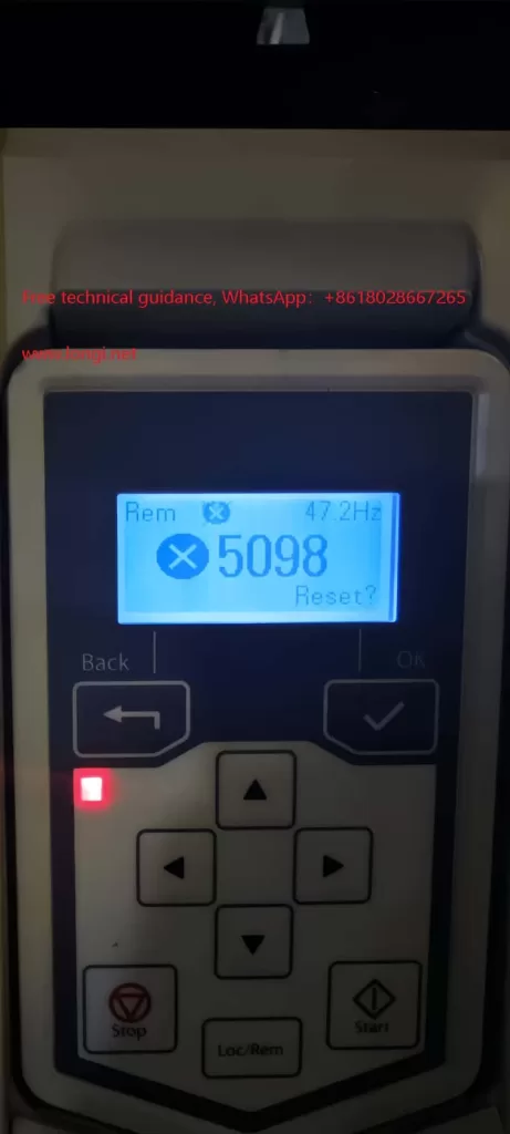
Physical picture of ACS530 with fault number 5098

I. Understanding the 5098 Alarm

In the ACS580 series, the 5098 alarm indicates “I/O Communication Lost,” signifying a failure in communication with the standard I/O (Input/Output) devices. This usually occurs when there is an issue with the communication link between the VFD’s I/O terminal board (where analog inputs like AI1 reside) and the main board. Similarly, in the ACS530 series, the 5098 alarm likely indicates a communication issue as well.

II. Possible Causes of the Fault

  1. Power Issues:
    • The 10V or 24V power supply on the I/O terminal board may be abnormal, leading to unstable or failed communication.
    • There may be short circuits, open circuits, or poor connections in the power lines.
  2. Hardware Connection Problems:
    • Connections between the I/O terminal board and the main board may be loose, have cold solder joints, or be corroded.
    • Terminals may have aged due to prolonged use, resulting in poor contact.
  3. Communication Module Failure:
    • The VFD’s I/O communication module may be damaged, preventing proper communication with the I/O terminal board.
  4. Software or Configuration Issues:
    • The VFD’s software configuration may have errors, affecting communication protocols or parameter settings.
    • Despite similarities in design and software between the ACS530 and ACS580 series, subtle differences in configuration may lead to unexpected alarms in the ACS530 under certain conditions.
Physical picture of ABB inverter ACS530

III. Fault Troubleshooting Steps

To address the 5098 alarm in the ACS530 VFD, follow these troubleshooting steps:

  1. Check Power Supplies:
    • Use a multimeter to verify the 10V and 24V power supplies on the I/O terminal board are functioning correctly.
    • Inspect power lines for completeness, shorts, or open circuits.
  2. Inspect Hardware Connections:
    • Disconnect all connections related to the I/O terminal board, reconnect them securely, and ensure they are tight.
    • Examine the connections between the I/O terminal board and the main board for looseness, cold solder joints, or corrosion, and make necessary repairs.
  3. Assess Communication Module:
    • If possible, test replacing the I/O communication module with an identical one to determine if it’s faulty.
  4. Reset and Restart:
    • Attempt to reset the VFD to clear the alarm.
    • If resetting fails, power off the VFD, wait for a while, and then power it back on to eliminate any software-related communication issues.
  5. Contact Technical Support:
    • If none of the above steps resolve the issue, contact ABB’s technical support team or a professional service provider for further diagnosis and repair.

IV. Conclusion

Despite the ACS530 series VFD manual’s lack of direct mention of the 5098 alarm, referencing similar ACS580 series documentation and contextual analysis enables understanding the likely fault type and appropriate troubleshooting methods. In practice, consider all potential causes

Posted on Leave a comment

CHF100A Series Vector Universal VFD Usage Guide:Usage of Operation Panel, Startup and Debugging of VFD Terminal Mode, Analysis and Solutions for VFD Fault Codes

I. Operation Panel (Keyboard) Usage

The operation panel (keyboard) of the CHF100A Series Vector Universal VFD serves as the primary interface for VFD control and parameter setting. Here are the basic keyboard operation methods:

  1. Power-on and Display:
    • Upon connecting the VFD’s power supply, the display on the operation panel will illuminate, showing the current status or default parameters.
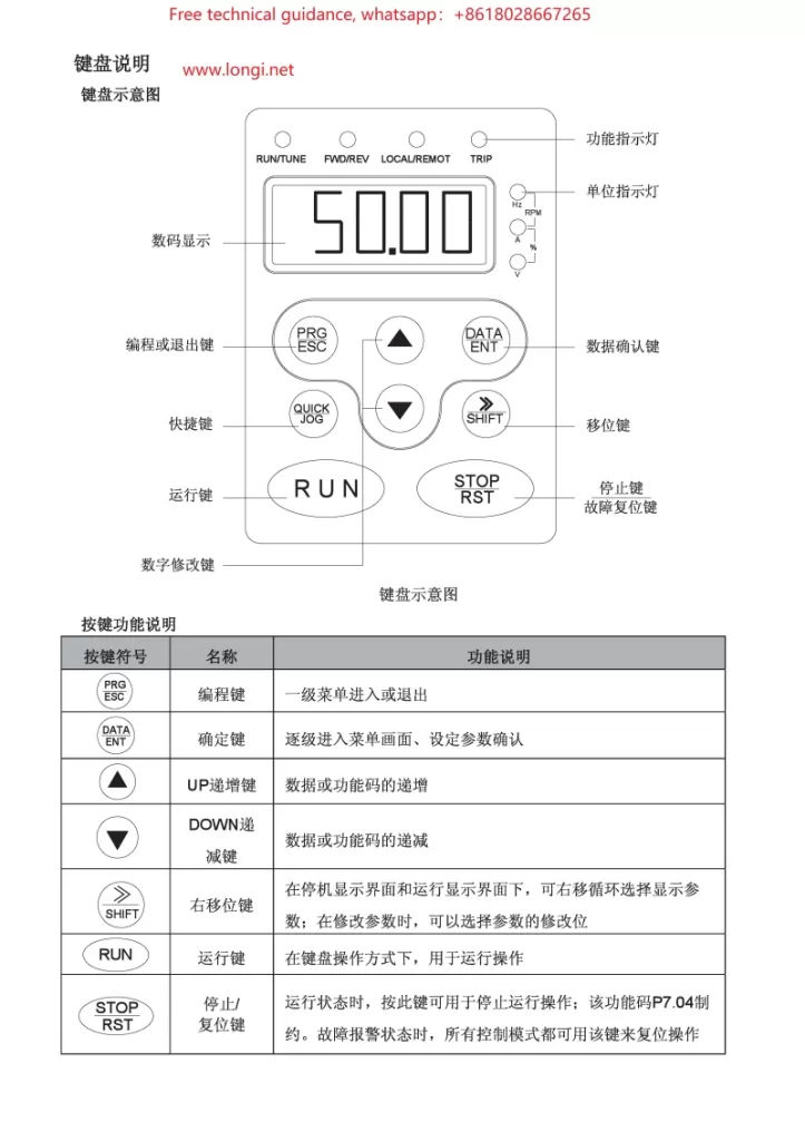
  2. Key Functions:
    • PRG: Programming key, used to enter or exit parameter setting mode.
    • SHIFT: Shift key, combined with numeric keys to select or modify high-order digits of parameters.
    • ESC: Escape key, used to exit the current setting or menu.
    • ENT: Enter key, used to confirm current settings or selections.
    • DATA: Data toggle key, used in some settings to switch between displaying different data items.
  3. Parameter Setting Procedure:
    • Press the PRG key to enter parameter setting mode.
    • Use arrow keys (if equipped) or SHIFT + numeric keys to select the desired parameter number.
    • Press the ENT key to enter the parameter’s setting interface.
    • Modify the parameter value using arrow keys or numeric keys.
    • Press the ENT key again to confirm the setting.
    • Press the ESC key to exit parameter setting mode.
INVT VFD CHF100A keyboard operation diagram

II. VFD Terminal Startup and Potentiometer Speed Regulation Wiring

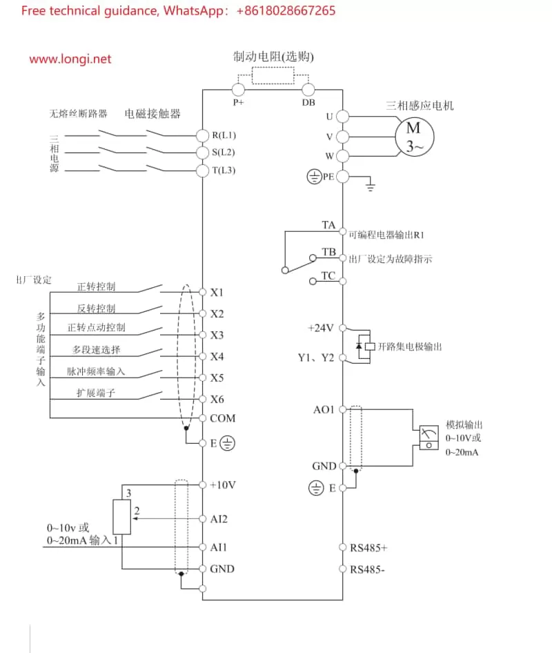
  1. Terminal Startup Wiring:
    • Refer to the electrical wiring diagram in the manual (typically around page 75) to locate the input terminals related to startup (e.g., S1, S2).
    • Connect the external startup signal (e.g., pushbutton switch, PLC output) to the corresponding startup terminals.
    • Configure parameters as needed to ensure the VFD recognizes and responds to these startup signals.
  2. Potentiometer Speed Regulation Wiring:
    • Locate the analog input terminals (e.g., AI1, AI2) on the VFD, which receive analog signals from the potentiometer.
    • Connect the wiper of the potentiometer to the AI1 or AI2 terminal, and the fixed terminal to the common ground (e.g., COM).
    • Adjust the potentiometer to vary the output signal, thereby controlling the VFD’s output frequency and motor speed.
CHF100A inverter wiring diagram

III. VFD Fault Code Analysis and Troubleshooting

When a CHF100A Series VFD encounters a fault, it displays the corresponding fault code on its screen. Here are some common fault codes, their analysis, and troubleshooting methods:

  1. OC (Overcurrent):
    • Cause: Excessive motor or load, output short circuit, faulty cabling or wiring.
    • Solution: Check the motor and load to ensure they are within normal ranges; inspect cabling and wiring for correctness; increase deceleration time or reduce acceleration current.
  2. OV (Overvoltage):
    • Cause: Excessive input voltage, inadequate deceleration time.
    • Solution: Verify that the input voltage meets specifications; increase deceleration time.
  3. UV (Undervoltage):
    • Cause: Insufficient input voltage, power supply failure.
    • Solution: Check the power supply voltage for normalcy; inspect power lines and fuses for integrity.
  4. OH (Overheating):
    • Cause: Elevated ambient temperature, poor ventilation, clogged heat sink.
    • Solution: Improve ventilation to enhance cooling, reduce ambient temperature; clean dust and debris from the heat sink.

Please note that these are exemplary analyses and solutions. Always refer to actual circumstances and detailed instructions in the manual. When dealing with any electrical fault, adhere strictly to safety procedures and consider power disconnection to avoid electrical shock risks.

Posted on Leave a comment

JACT AT500 Inverter Operation Guide and Fault Handling Summary

AT500 Inverter Operation Guide and Fault Handling Summary


I. AT500 Inverter Operation Panel Usage

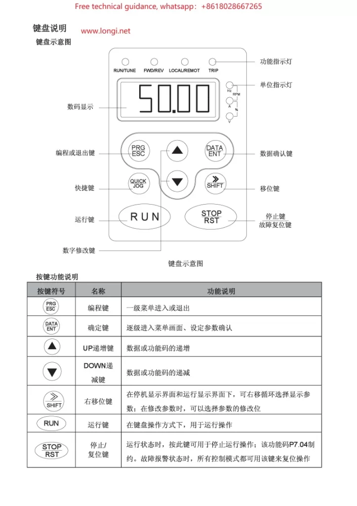
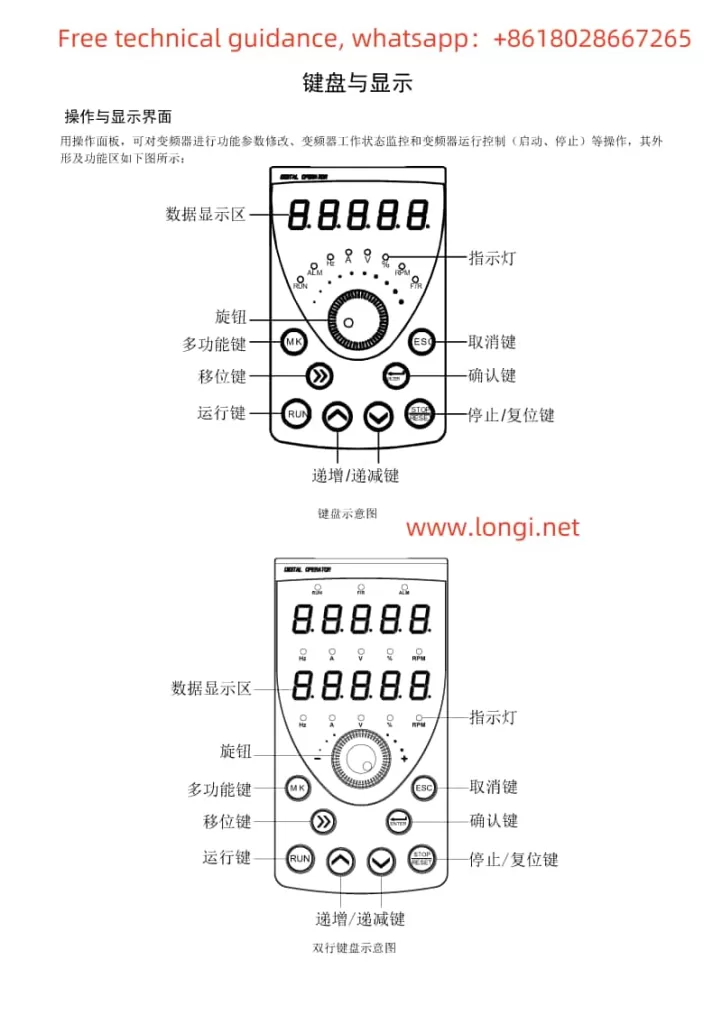
  1. Operation Panel Layout and Indicator Description:
    • Introduces the display, buttons (RUN, STOP/RES, MK, Λ, V, >>, etc.) on the operation panel and their functions.
    • Explains the meanings of various indicators (Run, Alm, Hz, A, V, %, rpm, F/R, etc.).
  2. Menu and Parameter Settings:
    • Describes the three-level menu mode (function parameter group, function code, function code modification) and its operation method.
    • Elaborates on how to view and modify various inverter parameters through the operation panel.
  3. Operation Mode Control:
    • Introduces starting the inverter via the RUN button and stopping it via the STOP/RES button.
    • Explains the jog operation function and its debugging applications.
Function diagram of AT500 inverter operation panel buttons

II. Terminal Control and External Potentiometer Debugging Mode Setup

  1. Terminal Control Setup:
    • Guides users to enter the F0 parameter group and set F0.02 to 1 to enable terminal control.
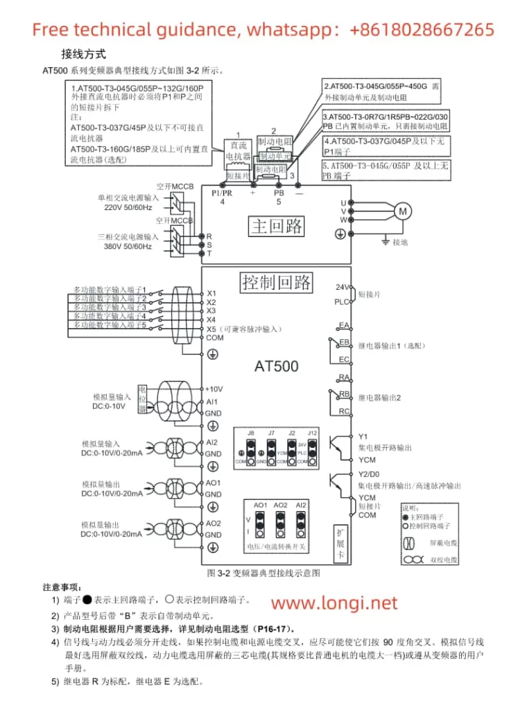
    • Demonstrates how to assign functions to each input terminal through the F2 parameter group and explains wiring requirements.
  2. External Potentiometer Debugging Mode:
    • Teaches users to set F0.03 or F0.04 to AI3 (keyboard potentiometer) to adjust the output frequency by rotating the potentiometer knob.
JACT AT500 inverter wiring diagram

III. Inverter Fault Code Classification and Troubleshooting Methods

  1. Overcurrent Faults (Err02-Err04):
    • Lists possible causes (output circuit short circuit, too short acceleration/deceleration time, etc.).
    • Provides solutions (check output circuit, adjust acceleration/deceleration time, etc.).
  2. Overvoltage Faults (Err05-Err07):
    • Analyzes fault causes (excessively high input voltage, external force during deceleration, etc.).
    • Offers remedies (adjust input voltage, eliminate external force during deceleration, etc.).
  3. Undervoltage Fault (Err09):
    • Describes fault causes (instantaneous power failure, low input voltage, etc.).
    • Suggests solutions (check input power supply, adjust voltage range, etc.).
  4. Overload Faults (Err10-Err11):
    • Indicates faults may be caused by excessive load, motor stall, etc.
    • Proposes reducing the load, checking the motor and mechanical conditions, etc.
  5. Input/Output Phase Loss Faults (Err12-Err13):
    • Analyzes fault causes (input power phase loss, faulty output wires or motor, etc.).
    • Offers advice on checking power and motor, troubleshooting peripheral faults, etc.
  6. Module Overheating Fault (Err14):
    • Explains fault causes (high ambient temperature, blocked air ducts, etc.).
    • Emphasizes the importance of reducing ambient temperature, cleaning air ducts, replacing fans, etc.
  7. Communication Fault (Err16):
    • Mentions possible causes (incorrect communication parameter settings, faulty communication cables, etc.).
    • Suggests checking communication parameters, cables, and the host computer.
Posted on Leave a comment

Key Points of Yufeng Inverter YF6800B Manual: Overview of Operation Methods, Terminal Start-up, External Potentiometer Speed Control Settings (with Specific Parameters), Fault Diagnosis and Resolution.

YF6800B Series Yufeng Inverter Manual Key Points Introduction

I. Operation Overview

The Yufeng Inverter YF6800B series boasts a straightforward operation process, primarily encompassing power-on/off and parameter settings. Upon powering on, ensure a stable power supply before initiating the inverter through the start button on the control panel or remote signals. To power off, first halt motor operation via the control panel or remote signals before cutting off the inverter’s power supply for device safety. Regarding parameter settings, users can navigate through the control panel’s buttons or connect to a computer using dedicated software to access the parameter setting mode, enabling precise adjustments to key parameters such as frequency, voltage, and current limits to meet diverse operational demands across various working conditions.

II. Terminal Start Configuration Method

Terminal start represents a commonly utilized control method for inverters, with its setup process encompassing wiring and parameter configuration.

  1. Wiring: Adhere to the wiring diagram outlined in the manual, connecting the inverter’s RUN (operate) and STOP (halt) terminals to the corresponding output terminals of external control devices like PLCs or buttons. Ensure secure and reliable connections, avoiding looseness or short circuits.
  2. Parameter Configuration: Navigate to the terminal control-related options within the inverter’s parameter settings to activate terminal control mode. Specific parameter configurations may include:
    • Input Point Function Configuration: Assign the RUN and STOP terminals’ corresponding input points to control start and stop operations, respectively.
    • Multi-speed Configuration (if applicable): Configure additional input points to correspond with distinct speed segments for multi-speed control.
    • Forward/Reverse Configuration (if required): Establish forward and reverse control logic to ensure the motor rotates in the anticipated direction.

III. External Potentiometer Speed Regulation Configuration Method

External potentiometer speed regulation offers a simple and intuitive means of speed adjustment, also encompassing wiring and parameter configuration.

  1. Wiring: Connect the external potentiometer’s output terminal to the inverter’s analog input terminal (e.g., AI1), with the potentiometer’s ends respectively wired to power and ground, forming a complete circuit. Select an appropriate power supply voltage and potentiometer resistance range to ensure precision and stability in speed regulation.
  2. Parameter Configuration: Locate the analog input-related options within the inverter’s parameter settings for the following configurations:
    • Input Source Configuration: Assign AI1 as the speed reference source.
    • Input Range Configuration: Match the inverter’s input range with the potentiometer’s output range.
    • Gain Configuration: Adjust the gain parameter to alter speed regulation sensitivity, facilitating smooth motor speed adjustment according to the potentiometer’s output.

IV. Fault Diagnosis and Resolution Methods

During the utilization of the Yufeng Inverter YF6800B, various faults may arise. Below are some common faults and their corresponding diagnosis and resolution methods:

  1. Overcurrent Protection: Inspect if the motor and load are excessively large or short-circuited, adjusting the load or replacing the motor as necessary. Additionally, verify if the inverter’s output current settings are reasonable.
  2. Overvoltage/Undervoltage Protection: Check if the input power supply voltage remains stable within the specified range. If voltage fluctuations are significant, implement voltage stabilization measures.
  3. Overheat Protection: Ensure the inverter’s cooling fan operates normally, cleaning dust and debris from the heat sink. If the ambient temperature is excessively high, adopt cooling measures.
  4. Communication Failure: Verify the secure and reliable connection of communication lines, along with accurate communication parameter settings. Attempt to restore communication by re-powering or restarting the device.
  5. Control Malfunction: Inspect if the control signal input is accurate and the control logic aligns with the set requirements. For complex control logic, utilize professional tools for fault location and analysis.

By adopting these methods, users can swiftly diagnose and resolve faults encountered during inverter operation, ensuring safe and stable device functioning.