Posted on Leave a comment

Maintenance ideas and methods for VFD switching power supply

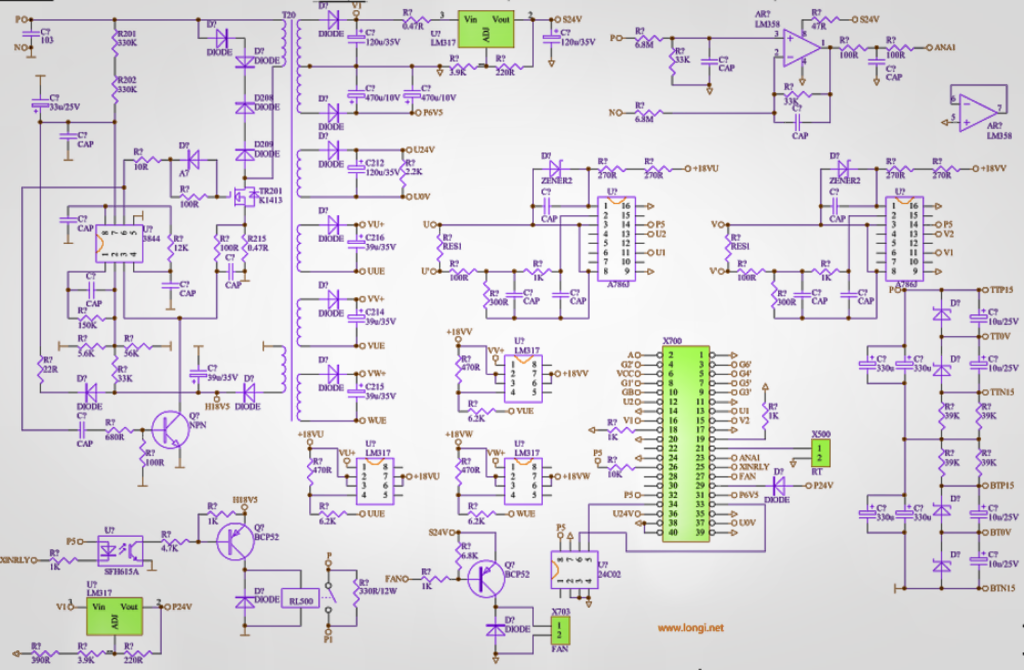
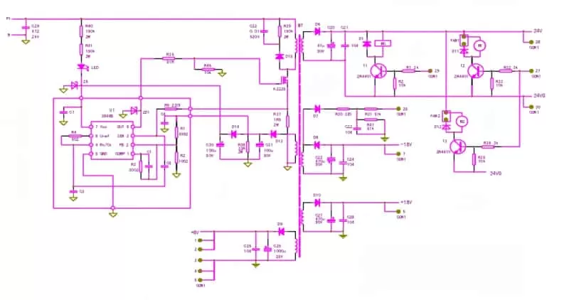
The switching power supply circuit of VFD can be completely simplified into the circuit model shown in the diagram, and the key elements in the circuit are included. And any complex switching power supply, after removing the branches, will still have a backbone like the one shown in the picture. In fact, in maintenance, it is necessary to have the ability to simplify complex circuits, and to identify these main threads in the seemingly disorderly extension of circuits. To learn from the skilled chef of Jieniu, train yourself that there is no overall switch power circuit in front of your eyes, only the direction of the various parts and veins – oscillation circuit, voltage stabilization circuit, protection circuit, and load circuit, etc.

Take a look at how many veins there are in the circuit.

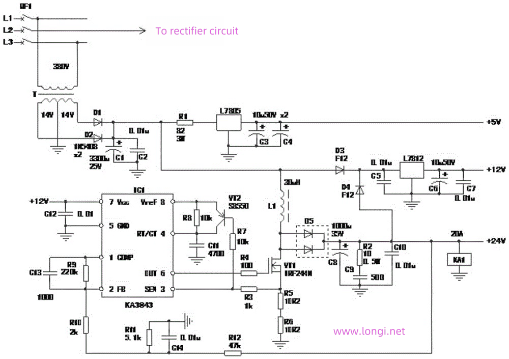
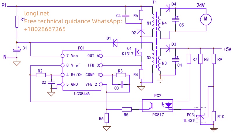
  1. 1.Oscillation circuit: The leakage source and R4 of the main windings N1 and Q1 of the switching transformer are the paths for the working current of the power supply; R1 provides starting current; The self powered windings N2, D1, and C1 form the power supply voltage for the oscillating chip. The normal operation of these three links is a prerequisite for the power supply to oscillate.

Of course, the 4-pin external timing components R2, C2, and PC1 chip itself of PC1 also constitute a part of the oscillation circuit.

  1. 2,.Voltage stabilizing circuit: The+5V power supply of N3, D3, C4, etc., and components such as R7-R10, PC3, R5, R6 constitute the voltage stabilizing control circuit.

Of course, the PC1 chip and peripheral components R3 and C3 on pins 1 and 2 are also part of the voltage stabilization circuit.

3.Protection circuit: The PC1 chip itself and the 3-pin peripheral component R4 form an overcurrent protection circuit; The parallel D2, R6, and C4 components on the N1 winding form the protection circuit of the IGBT; In essence, the voltage feedback signal of the voltage stabilizing circuit, the voltage stabilizing signal, can also be regarded as a voltage protection signal. However, the content of protecting the circuit is not limited to the protection circuit itself. The initiation and control of the protection circuit are often caused by abnormalities in the load circuit.

  1. 4.Load circuit: N3 and N4 secondary windings and subsequent circuits are all load circuits. The abnormality of the load circuit will involve the protection circuit and the voltage stabilizing circuit, causing the two circuits to make corresponding protection and adjustment actions.

The oscillation chip itself participates in and constitutes the first three circuits. If the chip is damaged, all three circuits will strike together. The maintenance of three or four circuits is carried out under the premise that the chip itself is normal. In addition, like playing chess, we should use a global perspective and systematic approach to diagnose faults, and see the essence through phenomena. If there is a stop vibration fault, it may not be caused by damage to the oscillation circuit components. It may be a voltage stabilization circuit fault or an abnormal load circuit, which causes the internal protection circuit of the chip to start controlling and stops the output of PWM pulses. It is not possible to completely isolate each circuit for maintenance, and the appearance of a faulty component may exhibit the effect of “pulling one engine and moving the whole body”.

The oscillation chip itself participates in and constitutes the first three circuits. If the chip is damaged, all three circuits will strike together. The maintenance of three or four circuits is carried out under the premise that the chip itself is normal. In addition, like playing chess, we should use a global perspective and systematic approach to diagnose faults, and see the essence through phenomena. If there is a stop vibration fault, it may not be caused by damage to the oscillation circuit components. It may be a voltage stabilization circuit fault or an abnormal load circuit, which causes the internal protection circuit of the chip to start controlling and stops the output of PWM pulses. It is not possible to completely isolate each circuit for maintenance, and the appearance of a faulty component may exhibit the effect of “pulling one engine and moving the whole body”.

Switching power supply circuits often exhibit the following three typical fault phenomena (combined with Figures 3 and 9):
A、 The secondary load supply voltage is 0V. After the frequency converter is powered on, there is no response, and there is no indication on the operation display panel. The measured voltage of 24V and 10V at the control terminal is 0V. If the charging resistance or pre charging circuit of the main circuit is intact, it can be determined that there is a switch power supply fault. The maintenance steps are as follows:

1.First, use the resistance measurement method to measure whether there is any breakdown or short circuit phenomenon in switch Q1, and whether there is an open circuit in the current sampling resistor R4. The easily damaged component of the circuit is the switch tube. When it is damaged, R4 will increase in resistance or open circuit due to impact. The G-pole series resistor and oscillation chip PC1 in Q1 are often damaged by strong electrical shocks and need to be replaced simultaneously; Check for short circuits in the load circuit and eliminate them.

2.If the damaged parts are replaced or there are short circuited components that have not been detected, a power on inspection can be conducted to further determine whether the fault is in the oscillation circuit or the voltage stabilizing circuit.

Inspection method:
a、 First, check if there is an open circuit in the starting resistor R1. After normal operation, use an 18V DC power supply to directly power on pins 7 and 5 of UC3844 to separately power on the oscillation circuit. Measure that pin 8 should have a 5V voltage output; The 6 pins should have a voltage output of about 1V. The oscillation circuit is basically normal, and the fault is in the voltage stabilizing circuit;
If the voltage output of pin 8 is 5V, but the voltage of pin 6 is 0V, check the external R and C timing components of pins 8 and 4, and the peripheral circuit of pin 6;
If the voltage measured on pins 8 and 6 is 0V, the UC3844 oscillation chip is broken and needs to be replaced.

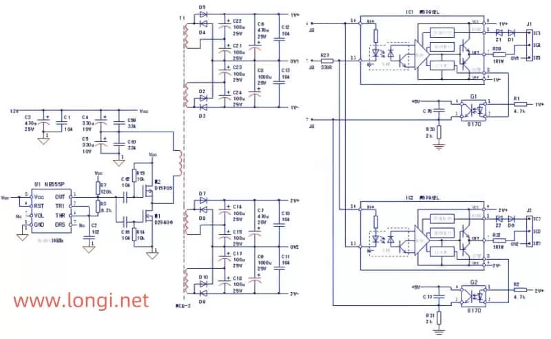
b、 Power on UC3844 separately and short circuit the input side of PC2. If the circuit vibrates, it indicates that the fault is in the peripheral circuit of the input side of PC2; The circuit still does not vibrate, check the PC2 output side circuit.

B、 Intermittent oscillation occurs in the switching power supply, where a “hiccup” or “squeaking” sound can be heard, or a “hiccup” sound cannot be heard, but when the display panel is operated, it lights up and turns off. This is a typical fault characteristic caused by abnormal load circuit, resulting in power overload and triggering overcurrent protection circuit action. The abnormal increase in load current causes a significant increase in the excitation current of the primary winding, forming a voltage signal of more than 1V at the current sampling resistor R4, which activates the internal current detection circuit of UC3844 and causes the circuit to stop vibrating; The overcurrent signal on R4 disappears, and the circuit starts vibrating again. This cycle repeats, causing intermittent oscillations in the power supply.

Inspection method:
a、 Measure the resistance values at both ends of the power supply circuit C4 and C5. If there is a short circuit, it may be due to a short circuit in the rectifier diodes D3 and D4; Observe the appearance of C4 and C5 for any bulging or liquid spraying, and remove them for inspection if necessary; There is no abnormality in the power supply circuit, which may be due to a short circuit fault component in the load circuit;
b、 Check the power supply circuit for any abnormalities, power on, and use the troubleshooting method to troubleshoot each power supply one by one. If the power supply terminal of the fan is unplugged, the switch power supply works normally, and the operation display panel displays normally, it indicates that the 24V cooling fan has been damaged; If the+5V power supply connector is unplugged or the power supply copper foil is cut off, and the switch power supply is working normally, it indicates that there are damaged components in the+5V load circuit.

C、 The supply voltage of the load circuit is too high or too low. The oscillation circuit of the switching power supply is normal, but the problem lies in the voltage stabilizing circuit.

The output voltage is too high, and the components of the voltage stabilizing circuit are damaged or inefficient, resulting in insufficient feedback voltage amplitude. Inspection method:
a、 Connect a 10k resistor in parallel to the output terminal of PC2, and the output voltage drops back. The output side voltage stabilizing circuit of PC2 is normal, and the fault lies in both the PC2 itself and the input side circuit;
b、 Parallel connection of a 500 Ω resistor on R7 results in a significant drop in output voltage. The optocoupler PC2 is in good condition, but the fault is low efficiency of PC3 or a change in the value of the external resistor component of PC3. On the contrary, it is PC2 defect.
If the load supply voltage is too low, there are three possible faults: 1. The load is too heavy, causing a decrease in output voltage; 2. Poor components of the voltage stabilizing circuit result in excessive voltage feedback signals; 3. The switch tube is inefficient, causing insufficient energy exchange in the circuit (switch transformer).

Inspection and repair methods:
a、 Remove the load circuits of the power supply branch one by one (note! Do not disconnect the load circuit by opening the power supply rectifier tube of that branch, especially the+5V power supply circuit with a voltage stabilizing feedback signal! The disappearance of the feedback voltage signal will cause abnormal increase in output voltage of each branch, and burn out large areas of the load circuit!) Determine whether the voltage drop is caused by excessive load; If the circuit returns to normal after cutting off a certain power supply, it indicates that the switching power supply itself is normal. Check the load circuit; Low output voltage, check the voltage stabilizing circuit.
b、 Check the resistance components R5-R10 of the voltage stabilizing circuit, and there is no change in value; Replace PC2 and PC3 one by one. If everything is normal, it indicates that the replacement components are inefficient and the internal resistance of conduction increases.
c、 If replacing PC2 and PC3 is ineffective, the fault may be low efficiency of the switch tube, or there may be problems with the switch and excitation circuit, which does not rule out the low efficiency of the internal output circuit of UC3844. Replace high-quality switch tubes and UC3844.

For general faults, the above troubleshooting methods are effective, but not necessarily 100% effective. If there are no abnormalities in the oscillation circuit, voltage stabilization circuit, or load circuit, but the circuit still has low output voltage, intermittent oscillation, or simply no response, this situation may occur. Don’t worry for now, let’s delve deeper into the cause of the circuit malfunction to help identify the faulty component as soon as possible. What other reasons can cause the circuit to not vibrate when the intermittent oscillation or stoppage of the circuit is not caused by the starting and stabilizing circuits?

(1) The R, D, and C circuits with parallel connection at both ends of the main winding N1 serve as a peak voltage absorption network, providing a discharge path for the magnetic field energy stored in the transformer during the switching period (reverse current channel of the switching tube), protecting the switching tube from overvoltage breakdown. When D2 or C4 experiences severe leakage or breakdown short circuit, the power supply is equivalent to adding a heavy load, causing the output voltage to drop significantly. U3844 lacks power supply, and the internal undervoltage protection circuit is activated, leading to intermittent oscillation of the circuit. Due to the parallel connection of components on the N1 winding, it is difficult to detect a short circuit and is often overlooked;
(2) Some switch mode power supplies have a protection circuit with an input power supply voltage (high voltage). Once the circuit itself malfunctions, the circuit will experience a false overvoltage protection action and the circuit will stop vibrating;
(3) Poor current sampling resistance, such as pin oxidation, carbonization, or increased resistance, can lead to an increase in voltage drop, resulting in false overcurrent protection and causing the circuit to enter an intermittent oscillation state;
(4) The rectifier diode D1 of the self powered winding is inefficient, and the forward conduction internal resistance increases, causing the circuit to fail to vibrate. Replacement testing is required;
(5) The quality factor of the switch transformer is reduced due to mold and moisture in the winding, and the original model transformer is used for replacement testing;
(6) The parameters of the R1 oscillation circuit vary, but no abnormalities are detected in the measurement, or the switching tube is inefficient. At this time, the circuit is checked and found to be normal, but it does not vibrate.

Repair method:
Change the existing parameters and status of the circuit to expose the fault! Try reducing the resistance value of R1 (not less than 200k Ω) so that the circuit can vibrate. This method can also be used as one of the emergency repair methods. Invalid, replace switch tube, UC3844, switch transformer test.
The output voltage is always slightly higher or lower, and cannot reach the normal value. Unable to detect any abnormalities in the circuit or components, almost all components in the circuit were replaced. The output voltage value of the circuit is still in a “barely and barely” state, sometimes seeming to work “normally”, but it makes people feel uneasy, as if they are neurotic, and I don’t know when an “abnormal performance” will occur. Don’t give up, adjust the circuit parameters to make the output circuit reach its normal value and reach its working state, so that we can rest assured. There are several reasons for the variation of circuit parameters:

  1. a、 Transistors are inefficient, such as a decrease in the amplification factor of the transistor, an increase in the internal resistance of conduction, an increase in the forward resistance of the diode, and a decrease in the reverse resistance;
  2. b、 The related dielectric loss, frequency loss, etc. of capacitors that cannot be measured with a multimeter;
  3. c、 Aging and parameter drift of transistors and chip devices, such as decreased light transfer efficiency of optocouplers;
  4. d、 Inductive components, such as switch transformers, have reduced Q values, etc;
  5. e、 The resistance variation of resistive components is not significant.
  6. f、 There are several factors involved in the above 5 reasons, forming a “comprehensive effect”.
  7. The “current” state of a circuit formed by various reasons is a “pathological” state. Perhaps we need to change our maintenance approach. Traditional Chinese medicine has a “dialectical treatment” theory, and we also need to use it. The next prescription is not to target a specific component, but to “regulate” the entire circuit, making it from “pathological” to “normal”. Just like this, the illness was treated with confusion and confusion.
  8. Repair method (slight adjustment of component values):

(1) Low output voltage:
a、 Increase R5 or decrease R6 resistance value; b、 Reduce the resistance values of R7 and R8 or increase the resistance values of R9.
(2) High output voltage:
a、 Reduce R5 or increase R6 resistance value; b、 Increase the resistance values of R7 and R8 or decrease the resistance values of R9.
The purpose of the above adjustments is to thoroughly inspect the circuit and replace inefficient components before proceeding. The purpose is to adjust the relevant gain of the stabilizing feedback circuit, so that the pulse duty cycle of the oscillation chip output changes, the energy storage of the switching transformer changes, and the output voltage of the secondary winding reaches the normal value, and the circuit enters a new “normal balance” state.
Many seemingly irreparable and difficult faults were repaired with ease after adjusting one or two resistance values.

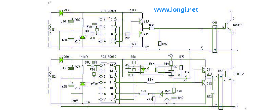
During maintenance, attention should be paid to the following issues: 1. During the inspection and repair process of the switching power supply, the power supply to the IGBT module of the three-phase output circuit should be cut off to prevent abnormal driving power supply and damage to the IGBT module; 2. When repairing faults with high output voltage, it is even more important to cut off the+5V power supply to the CPU motherboard to avoid abnormal or high voltage damage to the CPU, resulting in the CPU motherboard being scrapped. 3. Do not interrupt the voltage stabilizing circuit, as it will cause an abnormal increase in output voltage! 4. The diodes in switch mode power supply circuits, used for rectification and protection, are both high-speed diodes or Schottky diodes and cannot be replaced by ordinary IN4000 series rectifier diodes. 4. After the switch tube is damaged, it is best to replace it with the original model. With such a developed network, the source of goods is not a problem and can generally be purchased. Many things can be purchased at cheap prices on Taobao, pay attention to quality!

Posted on Leave a comment

Global Variable Frequency Drive (VFD) repair center

“Longi Electromechanical” has more than 20 years of experience in industrial control maintenance, and is one of the earliest companies engaged in VFD repair. Equipped with artificial intelligence AI maintenance instruments, it specializes in emergency repair of various equipment, with high technical efficiency. It has repaired more than 200,000 units of equipment, including ultrasonic, robot, charging pile, inverter,Variable Frequency Drive (VFD), touch screen, servo, intelligent instrument, industrial control machine, PLC and other products. General problems can be repaired on the same day. LONGI promises you that “if it can’t be repaired, we won’t charge you”. And it provides lifelong maintenance service and free technical consultation for inspection! For urgent repair consultation, please call the contact number or add WHATSAPP maintenance hotline: +8618028667265 Mr. Guo

From European and American brands to Japanese, Korean, and Taiwanese ones, until various domestic brands, we have repaired countless models and specifications of VFDs. In the process of serving our customers, we have continuously learned and accumulated maintenance experience to enhance our skills. We specialize not only in repairing VFDs but also in summarizing various maintenance experiences, elevating them to a theoretical level. We have published the book “VFD Maintenance Technology” and offered VFD maintenance training, thereby promoting the development of the VFD maintenance industry. Longi Electromechanical Company has repaired VFDs from the following brands:

European and American Brands

ABB drives, SEW drives, LUST VFD, LENZE VSD, Schneider drives, CT drives, KEB VSD, Siemens drives, Eurotherm VFD, G.E. VFD, VACON VSD, Danfoss VFD, SIEI VFD, AB VFD, Emerson VFD, ROBICON VFD, Ansaldo VFD, Bosch Rexroth VSD, etc.

Japanese Brands:

Fuji INVERTER, Mitsubishi INVERTER, Yaskawa INVERTER, Omron INVERTER, Panasonic INVERTER, Toshiba INVERTER, Sumner INVERTER, Tooka INVERTER, Higashikawa INVERTER, Sanken INVERTER, Kasia INVERTER, Toyo INVERTER, Hitachi INVERTER, Meidensha INVERTER, etc.

Taiwanese Brands:

Oulin INVERTER, Delta INVERTER, Taian INVERTER, Teco INVERTER, Powtran INVERTER, Dongling INVERTER, Lijia INVERTER, Ningmao INVERTER, Sanji INVERTER, Hongquan INVERTER, Dongli INVERTER, Kaichi INVERTER, Shenghua INVERTER, Adlee INVERTER, Shihlin INVERTER, Teco INVERTER, Sanchuan INVERTER, Dongweiting INVERTER, Fuhua INVERTER, Taian INVERTER (note: Taian is repeated, possibly a mistake in the original list), Longxing INVERTER, Jiudesongyi INVERTER, Tend INVERTER, Chuangjie INVERTER, etc.

Chinese Mainland brands:

Senlan Inverter, Jialing Inverter, Yineng Inverter, Hailipu Inverter, Haili Inverter, Lebang Inverter, Xinnuo Inverter, Kemron Inverter, Alpha Inverter, Rifeng Inverter, Shidai Inverter, Bost Inverter, Gaobang Inverter, Kaituo Inverter, Sinus Inverter, Sepaxin Inverter, Huifeng Inverter, Saipu Inverter, Weier Inverter, Huawei Inverter, Ansheng Inverter, Anbangxin Inverter, Jiaxin Inverter, Ripu Inverter, Chint Inverter, Delixi Inverter, Sifang Inverter, Geli Te Inverter, Kangwo Inverter, Jina Inverter, Richuan Inverter, Weikeda Inverter, Oura Inverter, Sanjing Inverter, Jintian Inverter, Xilin Inverter, Delixi Inverter, Yingweiteng Inverter, Chunri Inverter, Xinjie, Kemron-Bong Inverter, Nihonye Inverter, Edison Inverter

Other brands:
Migao VFD, Rongqi VFD, Kaiqi VFD, Shiyunjie VFD, Huichuan VFD, Yuzhang VFD, Tianchong VFD, Rongshang Tongda VFD, LG VFD, Hyundai VFD, Daewoo VFD, Samsung VFD, etc.

Longi Electromechanical Company specializes in the maintenance of VFDs and strictly requires its engineers to followlow standard operating procedures. Upon receiving a unit, the engineers carefully inspect its exterior and clarify any fault conditions with the customer before beginning work. Any removed circuit boards are cleaned using ultrasonic cleaning equipment. Repaired circuit boards are coated with high-temperature and high-pressure-resistant insulating paint, dried in a drying machine, and then reinstalled in the VFD, with measures taken to prevent corrosion and interference.

The repaired VFD will undergo a simulated operation with load using a heavy-load test bench to avoid any potential issues that may arise under actual load conditions on site.

When it comes to VFD maintenance, most cases are related to the equipment on site. Sometimes a standalone unit may have been repaired, but it doesn’t work properly when installed on site. In some cases, the problem lies with the system rather than the VFD itself. For such issues, if the customer requests on-site service, we will do our utmost to resolve the problem for them. If the location is far away, such as in another province, we can use tools like video conferencing and phone calls to allow our engineers to remotely diagnose and resolve the on-site issues for the customer.

Posted on Leave a comment

How to adjust the power rating of ABB’s ACS510/ACS550/ACS350/ACS355/ACH550 VFDs

With ABB’s ACS510/ACS550/ACS350/ACS355 VFDs, you can easily adjust the power rating through a straightforward process. Whether you want to upgrade a 1.1KW VFD to 5.5KW or vice versa, this flexibility allows you to set the power rating according to your needs. This feature is particularly useful when you have a limited number of VFD main boards, such as SMIO-01C, and need to adapt them to different power ranges. With this adjustment, you can ensure seamless operation even if a VFD in a different power range fails. These are not mentioned in the ABB AC drives PDF manual

  1. How to access and modify parameters:
    Open the parameter table, navigate to the deepest level of parameters, such as 0102, or any other displayed parameters. For example, if it says 9905, then hold the UP (arrow up), DOWN (arrow down), and RETURN (the button on the upper left next to LOC) buttons simultaneously for 3 seconds. You will notice a flash on the screen, and the top line of the screen should show “PARAMETERS+”.
  2. Expanding parameter groups:
    After that, exit and re-enter the parameter groups. Now, you will notice that the number of parameter groups has expanded from the original 99 to a maximum of 120. Navigate to parameter group 105.
  3. Modifying power capacity:
    To modify the relevant power capacity, follow these steps:
    • Find and modify parameter 10509. Change 105.09 to the desired current value and modify the corresponding power value accordingly (make sure it matches theVFD label. For example, if your inverter model is ACS510-01-017A-4, change it to 0174H; for ACS510-01-031A-4, change it to 0314H).
    • Set 10502 to 1 and confirm.
    • Set 10511 to 4012 and confirm.
    Please note that the order of modifications is crucial. If you make a mistake, you may need to start over.
  4. Verifying parameter changes:
    Finally, re-enter the parameter table and check if parameter 3304 (transmission capacity) has been correctly modified.
    To improve SEO performance, here are the optimized suggestions for the above text:

How to access and modify parameters:
Open the parameter table, navigate to the deepest level of parameters, such as 0102, or any other displayed parameters. For example, if it says 9905, then hold the UP (arrow up), DOWN (arrow down), and RETURN (the button on the upper left next to LOC) buttons simultaneously for 3 seconds. You will notice a flash on the screen, and the top line of the screen should show “PARAMETERS+”.

Expanding parameter groups:
After that, exit and re-enter the parameter groups. Now, you will notice that the number of parameter groups has expanded from the original 99 to a maximum of 120. Navigate to parameter group 105.

Modifying power capacity:
To modify the relevant power capacity, follow these steps:

Find and modify parameter 10509. Change 105.09 to the desired current value and modify the corresponding power value accordingly (make sure it matches the VFD label. For example, if your inverter model is ACS510-01-017A-4, change it to 0174H; for ACS510-01-031A-4, change it to 0314H).
Set 10502 to 1 and confirm.
Set 10511 to 4012 and confirm.
Please note that the order of modifications is crucial. If you make a mistake, you may need to start over.

Verifying parameter changes:
Finally, re-enter the parameter table and check if parameter 3304 (transmission capacity) has been correctly modified.

Just a reminder, the process of changing the power above has only been changed to the power of the ABB drive motherboard(SMIO-01C). The power of the drive board has not been changed, although it shows that it can be expanded. In fact, if the power of the power board has not been changed, the actual output power of the variable frequency drive (VFD) has not changed. At the same time, this method is only applicable to ACS510/ACS550/ACS350/ACS355/ACH550 VFDs and is not suitable for ACS800 series inverters. If you would like to know the power modification method for ACS800 inverters, please contact us directly.

Posted on Leave a comment

The circuit principle and modification and exchange method of frequency inverter transformer

The current transformers used in frequency inverter circuits, except for a few early products that used traditional transformers wound with through core inductor coils, are often integrated sealed current transformers made of Hall elements and pre current detection circuits (let’s call them electronic current transformers) in mature circuits. They are divided into standard and non-standard types, and the standard type uses specialized molded products in the market. For example, a 10A/1V current transformer generates a 1V signal voltage output for every 10A current in the circuit. Non standard type, designed and customized by the frequency converter manufacturer, cannot be used interchangeably. When damaged, it is generally necessary to replace the same model product provided by the original manufacturer. Of course, with deeper maintenance efforts, different models of current transformers can also be used for emergency repair or improvement, and later replaced.
Electronic current transformers often use some type of sealant for curing, which can cause damage and cannot be restored once removed. What kind of circuits are inside and whether they can be repaired or replaced, causing a lot of speculation. When I was repairing a Fuji frequency inverter, I replaced it with the main board of the TECO frequency inverter. When it was necessary to adjust the A/V ratio of the electronic current transformer, it had to be adjusted by the internal circuit of the transformer. Only then did I make up my mind and use a knife, a saw, and a lot of effort to dissect and map the internal circuits of the current transformers of these three types of frequency inverters. It was hard won.

An electronic current transformer is actually a circuit for a current/voltage converter. The Taian 7.5kW inverter current transformer circuit has a certain representativeness. The main body of the current transformer is also a circular hollow magnetic ring. The U, V, and W output lines of the frequency inverter pass through the iron core magnetic ring as the primary winding (small power models usually pass through multiple turns), and the magnetic ring generates magnetic field lines that vary in density with the output current of the frequency inverter. This magnetic ring has a gap in which a Hall element with four lead terminals is embedded. Hall elements are packaged in sheet form, and the magnetic field lines of the magnetic ring pass through the packaging end face of the Hall element, which is also known as the magnetic field line collection area (or magnetic induction surface). Hall elements convert changes in magnetic field lines into induced voltage outputs. The circuit consists of Hall elements and a precision dual operational amplifier circuit 4570. A constant current of mA (about 3-5mA) level must be added to the operation of the Hall element, and 4570A should be connected as a constant current source output mode to provide the mA level constant current required for the normal operation of the Hall element (the working current of the Hall element in this circuit is about 5.77 mA), which should be added to pins 4 and 2 of the Hall element; The induced voltage that varies with the output current at pins 1 and 3 of the Hall element is applied to the input terminals 2 and 3 of 4570b. Three pins are embedded in the reference voltage (zero potential point), and the change in input voltage of two pins is amplified and output by one pin (current detection signal). Electronic current transformers often have four terminal components, with two terminals supplying power to internal amplifiers of+15V and -15V, the other two terminals serving as signal output terminals, one terminal grounded, and one terminal serving as signal OUT terminal+ In addition to providing power for the dual operational amplifier IC4570, 15V and -15V are further stabilized by 6V to form a zero potential point introduced into the three pins of 4570. When the frequency converter is in a shutdown state, the ground measurement OUT point should be 0V. During operation, it will output an AC signal voltage below 4V in proportion to the output current.

After the electronic current transformer is damaged, it outputs a higher positive or negative DC voltage during static state (when the frequency inverter is shut down), which is mostly due to damage to the internal operational amplifier. Power on self-test of the frequency inverter, which displays a fault code (sometimes without a code in the manual), the frequency inverter will refuse to start or even parameter operation!
The current transformer circuit of TECO 3.7kW frequency converter uses a programmable operational amplifier chip. I have not yet found the model of this chip, but through modification tests, some characteristics of the circuit have been identified. According to the experiment, pin 2 is the constant current power supply terminal, pins 3 and 4 are the input terminals of the differential amplifier, and pin 13 is the signal output terminal. When short circuiting the solder gaps of pins 11, 12, and 13 step by step, the amplification factor shows a decreasing trend; When opening the circuit step by step, the amplification factor increases. This can adjust the amplification factor of the chip, making it easier to match frequency converters with different power outputs. I successfully applied the current transformer to a 45kW Fuji frequency Inverter by taking corresponding measures.
The voltage detection and current detection signals of the frequency converter may be applied by the program to control the output three-phase voltage and current – when the detection signal changes, the output three-phase voltage and current also change accordingly. When repairing or modifying the original circuit, be careful not to change the original circuit parameters. It is still recommended to use original accessories to repair the frequency converter while maintaining the original circuit form.

Posted on Leave a comment

Repair process of driving circuit for 22kW Delta frequency Inverter

After checking the drive circuit of the 22kW Delta VFD Drive and replacing it with a new module, the OC will jump upon startup. The module is newly replaced, and all six drive pulses are working properly. I don’t think it should be. Still checking the measurement, the six negative pressures driving the IC during shutdown are all normal, and the six excitation voltages are also normal after startup. It is necessary to first determine whether the fault is caused by the driver IC or the module.

It is necessary to first test the load carrying capacity of the six drive ICs, that is, to measure the trigger current value of their output. Connect a 15 ohm resistor in series to the output terminal, and then connect a 15 ohm resistor in series to the probe to limit the circuit current to around 0.5A. After the start signal is activated, its current output capacity is measured, and it can still provide a dynamic current of about 150mA even when the original trigger circuit is connected normally. The driving circuit of the V-phase lower arm IGBT tube only outputs about 40mA of current, which obviously cannot meet the excitation requirements of the IGBT tube. The root cause of the OC fault lies in this!
There seems to be a misconception about the driving method of IGBT tubes, especially high-power IGBT tubes: IGBT tubes are voltage signal excitation devices, not current type excitation devices. The driving signal only needs to meet the voltage amplitude, without requiring too much current driving capability! I have previously analyzed that even IGBT tubes are essentially current driven devices!
The output signals of the driving ICs (PC929 and PC923) of the machine are amplified by a complementary voltage follower and then supplied to the triggering terminals of the module. The push-pull amplifier was originally a pair of field-effect transistors, but due to the lack of the original type of transistor on hand, it has now been replaced with transistor pairs D1899 and B1261. After modification testing, it should be able to meet the excitation requirements. Check the V-phase lower arm circuit. The resistance from pin 11 (pulse output pin) of PC929 to the subsequent power amplifier circuit was originally 100 ohms, but now it has changed to over 100k, causing D1899 to be unable to fully conduct and the output driving current to be too small. After replacing the resistor, the output current is normal. After replacing the power transistor, the base resistance was not measured, resulting in this phenomenon.
By the way, I measured the negative current supply capacity of the driving circuit when cutting off negative pressure output. The probe is still connected in series with a 15 ohm resistor, and each circuit is around 30mA.
This leads to the conclusion that measuring the output voltage of the driving IC is not as direct and effective as measuring its output current. And it can expose the root cause of the malfunction. When the internal resistance of the circuit output increases due to certain reasons, measuring the driving voltage is often normal, which masks the truth of insufficient driving current.

Posted on Leave a comment

Repair of 22kW HC1 drive module malfunction

A 22kW HC1 drive, the fuse of the inverter module power supply series connection is broken, and no other abnormalities are found in the main circuit measurement. After installation, first send the inverter power supply to 24V and jump EOCn, which means overcurrent during acceleration and short circuit on the motor side. Obviously, there is still a malfunction in the module or driver part. It seems that it’s not just about replacing insurance.

Dismantle and recheck the driver circuit board. It was found that there was no positive excitation pulse output in one of the driver circuits. The power amplifier tube (lower tube) of the driver circuit was found to have broken down, and the voltage terminal of the module trigger terminal was continuously embedded on the negative pressure. After replacing the amplifier tube, the pulse circuit is normal.
Install the machine, connect to 24V power supply, and power on to trip EfbS, which means the fuse is blown. Remove the 24V power supply and replace the original fuse terminals with light bulbs in series, which will emit strong light upon power transmission. But after removing the trigger terminal during power outage, the individual measurement module was normal; Install the insurance and connect the inverter circuit to a 24V power supply. Start the frequency converter, and when the frequency rises to around 5Hz, the ECOn will still trip. I’m not sure if it’s still a problem with the module or the driver circuit.
Recheck the positive and negative voltage and current of the drive output, both are normal. Possible module malfunction. Simply remove all three modules and place them on the workbench for power testing along with the driver board. After powering on, it was detected that the negative pressure on one arm was low, about 2V. Disconnect the trigger terminal, the negative pressure returns to normal value, insert the module trigger terminal, and the negative pressure decreases again. Confirmed that the module was indeed damaged, replaced with a new module, and the fault was repaired.

Posted on Leave a comment

Repair of EDS1000 ENC VFDV Misleading Current Fault

A ENC EDS1000 11kW Inverter will trip to constant speed overcurrent when accelerating to above 40Hz during operation. But in reality, the operating current is much lower than the rated current, and after switching to other frequency converters, the motor runs normally. Check that the six inverter pulse outputs of the driving circuit are all normal. It is determined that the current transformer circuit detection is abnormal. Check the current detection circuit. The output signal of the current transformer is divided by a 3-ohm resistor and a 30 ohm resistor before being supplied to the motherboard. Suspecting that the current transformer is a non-standard product, an external voltage divider network was connected for adjustment. The partial voltage value may not be accurate enough, causing the current sampling value to be too large and mistakenly skipping the current fault. Or there may be drift in the output value of the internal circuit of the current transformer, which can also cause a false skip current fault.

The simplest method is to adjust the external voltage divider network of the current transformer. Reduce the voltage divider resistance value below it to meet the requirements of the subsequent circuit input voltage range. If conditions permit, the panel current display value can be monitored during operation, and the voltage divider resistance value can be adjusted to match the operating current value with the displayed current value. Often in the maintenance department, it is not possible to connect the frequency converter to the rated load for operation. Therefore, first replace the lower resistor with a 100 Ω potentiometer, and then adjust it to the appropriate position during on-site installation and operation.

Posted on Leave a comment

Hitachi VFD drive L300P75kW , after repair, installation still jumps “fault”,How to solve ?

A Hitachi L300P75kW Inverter was installed and tested on site after repairing the module fault. When powered on and started, E16.4 or E16.2 jumps. The cause of the fault is a momentary open circuit in the power supply. Stop the machine and measure the three-phase 380V power input. All three phases have 380V and are quite balanced. During operation, when measuring the three-phase output circuit, there is an unstable voltage value in one phase, with fluctuations ranging from 280V to around 350V. The voltage detection circuit of this machine detects the input voltage of T and S phases in the input power supply. When the power grid pollution flash exceeds 15ms, it will protect and shut down. It was determined that the air switch supplying power to the frequency converter had poor contact with one phase, causing the frequency converter to trip E16.4 or E16.2 faults. Upon disassembly and inspection, it was confirmed that a set of contacts had been severely burned out.
Repair after replacing the power switch.

This fault is in a stationary state or a low current state, and due to the virtual connection of the air switch, the abnormal input voltage cannot be detected at all. Only visible when turned on. But due to the abnormal detection of the frequency Inverter, it immediately shuts down for protection. Sometimes, if there is no time to detect, the frequency converter has already stopped. So it’s not easy to detect. It took some effort.

Posted on Leave a comment

Test run failure of the CHRH-415AEE Rihong VSD

Repairing the Shanghai Rihong CHRH-415AEE 1.5kW machine, the user reported unstable output and motor jumping. The output module and output module are both normal. After cutting off the power supply to the inverter module, in order to check the quality of the inverter pulse conveying circuit (including the driving circuit), they were installed as a complete machine on the maintenance bench (without the machine cover installed) and powered on for inspection. The operation panel displays normally, but when starting the operation, it jumps E OH means overheating. The thermal signal output terminals of the short-circuit modules T1 and T2 are invalid. Disconnect the thermal signal terminal and connect the original wiring terminal to the potentiometer for voltage regulation. The test is also ineffective. Check the internal circuit diagram of the module. The terminal is only equipped with a thermistor (10k at zero degrees Celsius), which is connected to an external+5V resistor to divide the voltage and directly send the signal to the CPU. According to room temperature, this partial pressure point should be below 2.5V. The measured voltage is 2.3V, and the built-in thermal element and circuit should be normal.

Later, it was discovered by chance that a small square shielding iron sheet was wrapped around the back of the operation panel. When pressing the operation panel, one corner of this iron sheet touched the 41 pin of the CPU, which happened to be the input pin for the overheat signal. Therefore, pressing the button on the operation panel inputs a module overheating signal (disturbance generated) to the CPU, which is truly a coincidence.
A piece of cardboard is placed between the operation panel and the motherboard circuit, so that when operating the panel, it no longer jumps OH fault code. The fault was quickly identified as a faulty driver circuit, and the machine was repaired by replacing it with a driver IC.

Posted on Leave a comment

Several major causes of damage to the inverter output module of the VSD drive

A. Damage caused by abnormal load
Indeed, the protection circuit of the frequency converter is already quite complete. For the protection of expensive inverter modules, various inverter manufacturers have put a lot of effort into their protection circuits, from output current detection to IGBT voltage drop detection in the drive circuit, and strive to implement the fastest overload protection with the fastest strain rate! From voltage detection to current detection, from module temperature detection to phase loss output detection, there has not been a protection circuit for any particular electrical appliance yet. A frequency converter has been focused and invested in this approach. When salespeople talk about the performance of frequency converters, they must also mention the protection function of the frequency converter. They often unconsciously promise users that with the comprehensive protection function of the frequency converter, your motor will not be easily burned. This salesperson doesn’t know that this promise will bring him great passivity!

Does the motor really not burn when using a frequency converter? My answer is: compared to power supply, using a frequency converter makes it easier for the motor to burn, and the motor is prone to burning, making it easier for the inverter module of the frequency converter to be “reimbursed” together. The sensitive overcurrent protection circuit of the frequency converter is at a loss here and has no effect at all. This is a major external cause of damage to the frequency converter module. Listen to me explain the truth behind it.
A motor can operate at power frequency, although the operating current is slightly higher than the rated current, there is a certain temperature rise during long-term operation. This is a faulty motor that can indeed run before it burns out. But after connecting to the frequency converter, frequent overloads may occur, making it impossible to operate. It doesn’t matter yet.
A motor that can operate in power frequency mode and has been used normally by the user for many years. Please pay attention to the word “many years”. Users may think of saving electricity bills or need to undergo frequency conversion modifications due to process modifications. But after connecting to the frequency converter, there will be frequent OC faults, which is good. The protection has stopped and the module is not damaged. What’s scary is that the frequency converter didn’t immediately trip the OC fault, but was running for no reason – after only three or two days of operation, the module exploded and the motor burned out. The user relied on the salesperson: the quality of the frequency converter you installed is poor, burned my motor, you want to compensate my motor!
Prior to this, the motor seemed to have no problems and was running well. The operating current was measured because the load was relatively light, reaching half of the rated current; Tested three-phase power supply, 380V, balanced and stable. It really seems like the damage to the frequency converter, along with the damage to the motor.
If I were present, I would be fair and impartial: don’t blame the frequency converter, it’s because your motor is already “critically ill” and suddenly malfunctioned, accompanied by damage to the frequency converter!
A motor that has been in operation for many years, due to temperature rise and moisture, the insulation degree of the winding has greatly decreased, and even has obvious insulation defects, which are at the critical point of voltage breakdown. In the case of power supply at power frequency, the input voltage of the motor winding is a three-phase 50Hz sine wave voltage, and the induced voltage generated by the winding is also relatively low. The surge component in the circuit is small, and the decrease in the insulation degree of the motor may only bring about inconspicuous “leakage current”. However, the voltage breakdown phenomenon has not yet occurred between the turns and phases of the winding, and the motor is still “operating normally”. It should be said that as the degree of insulation aging deepens, even under power supply at power frequency, it is believed that in the near future, the motor will eventually burn out due to voltage breakdown between phases or windings caused by insulation aging. But the problem is, it hasn’t burned down yet.

After connecting to the frequency converter, the power supply conditions of the motor become “harsh”: the PWM waveform output by the frequency converter is actually a carrier voltage of several kHz or even more than ten kHz, and various components of harmonic voltage will also be generated in the motor winding power supply circuit. According to the characteristics of the inductor, the faster the change rate of the current flowing through the inductor, the higher the induced voltage of the inductor. The induced voltage of the motor winding has increased compared to the power frequency supply. Insulation defects that cannot be exposed during power supply at power frequency are caused by the inability to withstand the impact of induced voltage under high-frequency carriers, resulting in voltage breakdown between turns or phases of the winding. The sudden short circuit of the motor winding was caused by a phase to turn short circuit in the motor winding. During operation, the module exploded and the motor burned out.
In the initial stage of start-up, due to the low output frequency and voltage of the frequency converter, when there is a fault in the load motor, although it causes a large output current, this current is often within the rated value. The current detection circuit acts in a timely manner, and the frequency converter implements a protective shutdown action, so there is no risk of module damage. But if the three-phase output voltage and frequency reach high amplitudes under full speed (or near full speed) operation, if there is voltage breakdown phenomenon in the motor winding, it will instantly form a huge surge current. Before the current detection circuit acts, the inverter module cannot withstand it and will explode and be damaged.
From this, it can be seen that protective circuits are not omnipotent, and any protective circuit has its own weaknesses. The frequency converter is unable to effectively protect the motor winding from sudden voltage breakdown during full speed operation. Not only the frequency converter protection circuit, but any motor protector cannot effectively protect against such sudden faults. When such sudden faults occur, it can only be declared that the motor has indeed passed away.
This type of fault is a fatal blow to the inverter output module of the frequency converter and cannot be avoided.

其它由供电或负载方面引起的原因,如过、欠压、负载重、甚至堵转引起的过流等故障,在变频器的保护电路正常的前提下,是能有效保护模块安全的,模块的损坏机率将大为减小。在此不多讨论。
B、由变频器本身电路不良造成的模块损坏
1、 由驱动电路不良对模块会造成一级危害
由驱动电路的供电方式可知,一般由正、负两个电源供电。+15V电压提供IGBT管子的激励电压,使其开通。-5V提供IGBT管子的截止电压,使其可靠和快速的截止。当+15V电压不足或丢失时,相应的IGBT管子不能开通,若驱动电路的模块故障检测电路也能检测IGBT管子时,则变频器一投入运行信号,即可由模块故障检测电路报出OC信号,变频器实施保护停机动作,对模块几乎无危害性。
而万一-5V截止负压不足或丢失时(如同三相整流桥一样,我们可先把逆变输出电路看成一个逆变桥,则由IGBT管子组成了三个上桥臂和三个下桥臂,如U相上桥臂和U相下桥臂的IGBT管子。), 当任一相的上(下)桥臂受激励而开通时,相应的下(上)桥臂IGBT管子则因截止负压的丢失,形成由IGBT管子的集-栅结电容对栅-射结电容的充电,导致管子的误导通,两管共通对直流电源形成了短路!其后果是:模块都炸飞了!
截止负压的丢失,一个是驱动IC损坏所造成;还有可能是驱动IC后级的功率推动级(通常由两级互补式电压跟随功率放大器组成)的下管损坏所造成;触发端子引线连接不良;再就是驱动电路的负供电支路不良或电源滤波电容失效。而一旦出现上述现象之一,必将对模块形成致命的打击!是无可挽回的。
2、脉冲传递通路不良,也将对模块形成威胁
由CPU输出的6路PWM逆变脉冲,常经六反相(同相)缓冲器,再送入驱动IC的输入脚,由CPU到驱动IC,再到逆变模块的触发端子,6路信号中只要有一路中断——
a、变频器有可能报出OC故障。逆变桥的下三桥臂IGBT管子,导通时的管压降是经模块故障检测电路检测处理的,而上三桥臂的IGBT管子,在小部分变频器中,有管压降检测,大部分变频器中,是省去了管压降检测电路的。当丢失激励脉冲的IGBT管子,恰好是有管压降检测电路的,则丢失激励脉冲后,检测电路会报出OC故障,变频器停机保护;
b、变频器有可能出现偏相运行。丢失激励脉冲的该路IGBT管子,正是没有管压降检测电路的管子,只有截止负压存在,能使其可靠截止。该相桥臂只有半波输出,导致变频器偏相运行,其后果是电机绕组中产生了直流成分,也形成较大的浪涌电流,从而造成模块的受冲击而损坏!但损坏机率较第一种原因为低。
若此路脉冲传递通路一直是断的,即使模块故障电路不能起到作用,但互感器等电流检测电路能起到作用,也是能起到保护作用的,但就怕这种传递通路因接触不良等故障原因,时通时断,甚至有随机性开断现象,电流检测电路莫名所以,来不及反应,而使变频器造成“断续偏相”输出,形成较大冲击电流而损坏模块。
而电机在此输出状态下会“跳动着”运行,发出“咯楞咯楞”的声音,发热量与损耗大幅度上升,也很容易损坏。
3、电流检测电路和模块温度检测电路失效或故障,对模块起不到有效地过流和过热保护作用,因而造成了模块的损坏。
4、主直流回路的储能电容容量容量下降或失容后,直流回路电压的脉动成分增加,在变频器启动后,在空载和空载时尚不明显,但在带载起动过程中,回路电压浪起涛涌,逆变模块炸裂损坏,保护电路对此也表现得无所适从。
对已经多年运行的变频器,在模块损坏后,不能忽略对直流回路的储能电容容量的检查。电容的完全失容很少碰到,但一旦碰上,在带载启动过程中,将造成逆变模块的损坏,那也是确定无疑的!
C、质量低劣、偷工减料的少部分国产变频器,模块极易损坏
这是国民劣根性的一种体现,民族之痒啊。不错,近几年变频器市场的竞争日趋激烈,变频器的利润空间也是越来越狭窄,但可以通过技术进步,提高生产力等方式来提高自身产品的竞争力。而采用以旧充新、以次充好、并用减小模块容量偷工减料的方式,来增加自己的市场占有率,实是不明智之举呀,纯属一个目光短浅的短期行为呀。
1、质量低劣、精制滥造,使得变频器故障保护电路的故障率上升,逆变模块因得不到保护电路的有效保护,从而使模块损坏的机率上升。
2、逆变模块的容量选取,一般应达到额定电流的2.5倍以上,才有长期安全运行的保障。如30kW变频器,额定电流为60A,模块应选用150A至200A的。用100A的则偏小。但部分生产厂商,竟敢用100A模块安装!更有甚者,还有用旧模块和次品模块的。此类变频器不但在运行中容易损坏模块,而且在启动过程中,模块常常炸裂!现场安装此类变频器的工作人员都害了怕,远远地用一支木棍来按压操作面板的启动按键。
容量偏小的模块,又要能勉强运行,模块超负荷工作,保护电路形成同虚设(按变频器的标注功率容量来保护而不是按模块的实际容量值来保护),模块不出现频繁炸毁,才真是不正常了。
这类机器,因价格低廉,初上市好像很“火”,但用不了多长时间,厂家也只有倒闭一途了。

The reason for the third type of module damage should not have been a single cause. Hopefully, in the near future, the only reasons for module damage will be the first two.
For domestic frequency converters, sometimes it’s just a piece of mouse manure that spoils a pot of soup. Many frequency converters are also quite good, not inferior to foreign products, and they are of good quality and affordable.