
A factory has a 5.5 kW submersible pump. To facilitate water volume adjustment and energy-saving operation, an electrician proposed using a VFD to drive the pump.
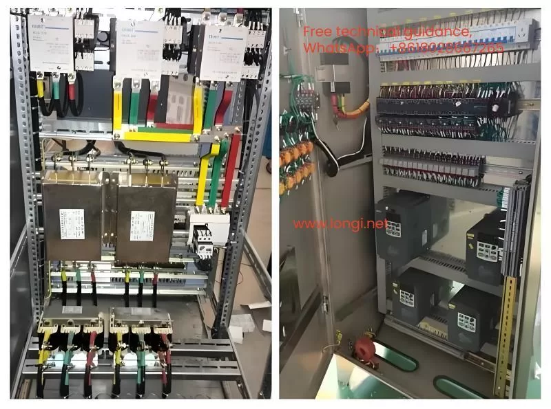
The task was taken on by Mr. Zhang, a friend of the electrician. For safety, Mr. Zhang selected a 7.5 kW VFD from a reputable brand. This brand’s VFDs are widely used in various industries such as plastics, chemicals, and wood processing without significant issues, indicating decent quality. The VFD control box was installed in the boiler room, with power sourced from the workshop distribution panel. The three-phase voltage balance was excellent, maintaining within 380V ±5%. During the trial run, the VFD did not need to operate at full speed, running around 30Hz with the working current at half of the VFD’s rated current. Mr. Zhang was confident that the VFD would operate safely for a long time.
However, three days later, the factory’s electrician called Mr. Zhang, reporting that the VFD had stopped, and the control panel was unresponsive, indicating no power. Surprised, Mr. Zhang visited the site and confirmed the issue. Assuming a quality problem with the VFD, he replaced it with another 7.5 kW VFD from the supplier and sent the defective one for repair.
This time, the VFD failed after just a day and a half. Frustrated, Mr. Zhang called the supplier to complain and replaced the VFD with another brand. He again checked the operating voltage and current, which were similar to the initial installation, indicating no issues with the pump or power supply. Mr. Zhang concluded that the first batch of VFDs might have had quality defects and hoped the new brand would solve the problem.
Unexpectedly, the newly installed VFD also failed within hours, with the factory’s electrician calling Mr. Zhang again. The recurring issue led to reprimands from the factory boss to the electrician, who then passed the blame to Mr. Zhang. Baffled, Mr. Zhang inspected the three faulty VFDs. He found that two had open circuits between the R and P1 (external brake resistor terminal), possibly due to damaged charging resistors, which indicated rectifier circuit issues. The third VFD had a short circuit between R and S, suggesting a failed rectifier module. However, the inverter modules in all three VFDs were intact. The damages seemed to result from power surges, not load-related issues, as the three-phase supply voltage and input current were normal. Having worked with VFDs for several years, Mr. Zhang found this problem unprecedented.
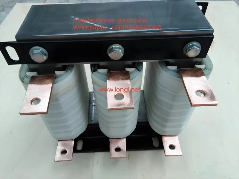
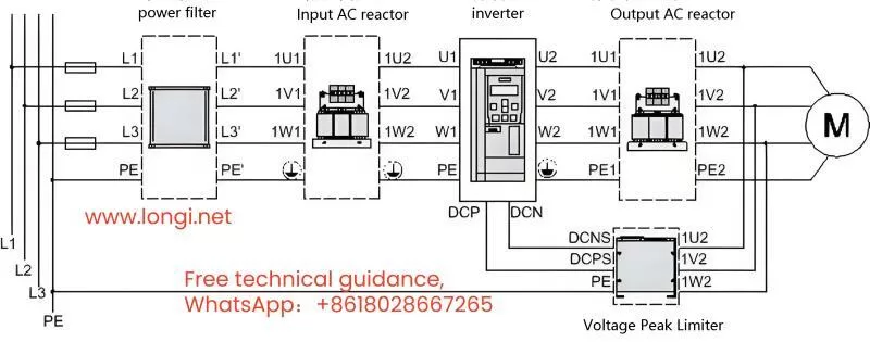
In desperation, Mr. Zhang called his friend, electrician Mr. Li, for advice. Mr. Li suggested installing a three-phase input reactor before the VFD’s power terminals to solve the problem.
Mr. Zhang inquired about the cause of the failures. Mr. Li explained three potential reasons related to the power supply:
1. The submersible pump continued to operate after work hours for employee showers, meaning a 630 kVA transformer supplied a 7.5 kW VFD, causing a significant capacity disparity. The VFD’s input current contained high harmonic components, generating large rectifier inrush currents that damaged the rectifier module and charging resistor during startup.
2. The workshop distribution panel might have parallel capacitor compensation cabinets. The start and stop of large motors (above 100 kW) and the switching currents of capacitors created harmful voltage spikes and inrush currents, impacting the VFD.
3. The same power line might have other large VFDs, soft starters, or DC speed controllers. The nonlinear rectifier currents from these devices severely distorted the power supply waveform, increasing harmful harmonics and deteriorating power quality.
Mr. Li noted that input reactors, often depicted in VFD wiring diagrams, are frequently omitted during installation to save costs, leading to such issues.
Mr. Zhang didn’t have ready-made three-phase reactors and needed an immediate solution. Mr. Li suggested using XD1 series chokes from old capacitor compensation cabinets as reactors, which could suppress inrush currents effectively. Mr. Zhang contacted several suppliers but learned that most manufacturers had stopped producing these chokes.
Under pressure, Mr. Zhang reached out to Mr. Li again, demanding a solution. Mr. Li, while having lunch, suggested using current transformers (CTs), which Mr. Zhang likely had. Any CT, regardless of size, with a rated current of 5A, could be used. CTs with more winding turns (e.g., 50/5) would offer better inrush current suppression and filtering but might have a higher voltage drop. Conversely, CTs with fewer turns (e.g., 250/5) would have a smaller voltage drop but less effective smoothing. Depending on the VFD’s rated current, Mr. Li recommended using three CTs per phase or two if the running current was around 7A. CTs would provide better inductance and performance than XD1 chokes.
After installing CT-based “input reactors,” the VFD’s input current became stable, reducing harmonics and voltage spikes, ensuring safer operation.
Months later, Mr. Zhang checked with the factory electrician, who confirmed that the VFD had been operating normally. Mr. Zhang realized the VFD failures were due to power supply issues, not the VFD quality. He felt vindicated and teased the electrician about owing him a drink for resolving the issue.