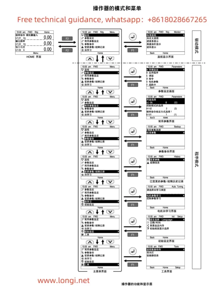
I. Detailed Explanation of Operator Panel Functions

The operator panel of the Yaskawa GA700 Inverter serves as the primary interface for user interaction, providing a wealth of functions and setting options. Below are the main functions and operation instructions for the operator panel:
- Display and Setting Functions
- Monitoring Display: The operator panel can display various status information of the inverter, such as frequency command, output frequency, current, voltage, etc. Users can select the desired monitoring item using the up, down, left, and right keys.
- Parameter Settings: Through the operator panel, users can access and modify various inverter parameters to meet different application requirements. Press the “MENU” key to enter the menu, then use the up and down keys to select the desired parameter, and press the “ENTER” key to enter the parameter setting interface.
- Restoring Factory Default Parameters
If it is necessary to restore the inverter parameters to their factory defaults, follow these steps:- Press the “MENU” key to enter the menu.
- Use the up and down keys to select the “Tools” menu, then press the “ENTER” key to enter.
- In the “Tools” menu, use the up and down keys to select the “Parameter Initialization” option, then press the “ENTER” key to enter.
- Select “Factory Default Initialization” and press the “ENTER” key to confirm. The system will prompt for confirmation; press the “YES” key to initialize, and the inverter parameters will be restored to their factory defaults.
- Setting External Terminal Start
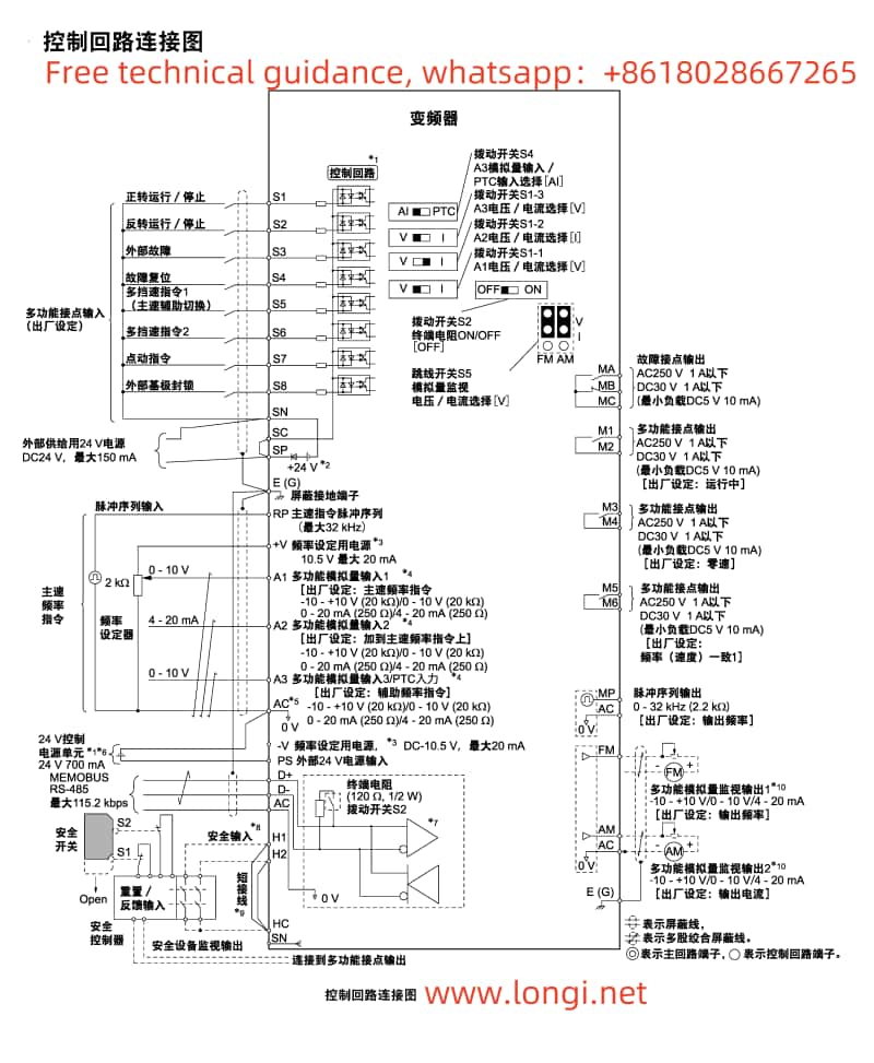
External terminal start refers to controlling the start and stop of the inverter through external signals (such as buttons, switches, etc.). Follow these steps to set external terminal start:- Ensure that the external control circuit is correctly wired.
- Enter the “Application” menu on the operator panel and select “Frequency Command Source 1” (b1-01).
- Set b1-01 to “0”, indicating that the operator panel is used to input the run command. If external terminal start is desired, set it to “2” (indicating that the control circuit terminal is used to input the run command).
- Set other related parameters as needed, such as the function selection for the external start terminal (H1-xx parameter).

II. Settings for External Terminal Start and External Potentiometer Speed Control
- External Terminal Start Settings
The settings for external terminal start include wiring and parameter settings:- Wiring Steps:
- Connect one contact of the external start button or switch to the “RUN” terminal of the inverter (e.g., terminal S1).
- Connect the other contact to the common terminal of the inverter (e.g., terminal CM).
- Parameter Setting Steps:
- Enter the “Application” menu on the operator panel and select “Frequency Command Source 1” (b1-01).
- Set b1-01 to “2”, indicating that the control circuit terminal is used to input the run command.
- Enter the “Multi-function Input Terminals” menu (H1-xx), select the corresponding terminal (e.g., H1-01), and set its function to “Run Command” (e.g., set value “1”).
- Wiring Steps:
- External Potentiometer Speed Control Settings
External potentiometer speed control allows users to adjust the output frequency of the inverter by rotating the potentiometer, thereby controlling the motor speed.- Wiring Steps:
- Connect the three terminals of the potentiometer to the “AI1” (Analog Input 1) terminal of the inverter, the common terminal (e.g., terminal CM), and ground (GND), respectively.
- Parameter Setting Steps:
- Enter the “Application” menu on the operator panel and select “Frequency Command Source 1” (b1-01).
- Set b1-01 to “1”, indicating that analog input is used as the frequency command.
- Enter the “Multi-function Analog Input” menu (H3-xx), select “Terminal A1 Function Selection” (H3-02), and set it to “Main Speed Frequency Command” (set value “0”).
- Adjust “Terminal A1 Input Gain” (H3-03) and “Terminal A1 Input Offset” (H3-04) as needed to match the output range of the potentiometer and the frequency command range of the inverter.
- Wiring Steps:
III. Inverter Fault Codes and Handling Methods
When the Yaskawa GA700 Inverter encounters a fault, it will display the corresponding fault code. Below are some common fault codes, their meanings, and handling methods:
- oC (Overcurrent)
- Meaning: The inverter output current exceeds the rated value.
- Handling Method: Check if the motor load is too heavy, if there are short circuits or grounding faults, and adjust inverter parameters (such as acceleration/deceleration time, torque limit, etc.).
- oV (Overvoltage)
- Meaning: The DC bus voltage of the inverter is too high.
- Handling Method: Check if the input power supply is stable, if there are issues with the braking resistor (overheating or damage), and adjust inverter parameters (such as deceleration time, overvoltage suppression function, etc.).
- oH (Overheat)
- Meaning: The internal temperature of the inverter is too high.
- Handling Method: Check if the installation environment of the inverter is well-ventilated, if there is dust accumulation or blocked heat sinks, clean the heat sinks, and check if the cooling fan is working properly.
- FbL (PID Feedback Lost)
- Meaning: The feedback signal is lost in PID control.
- Handling Method: Check if the PID feedback loop is correctly wired, if the feedback sensor is working properly, and adjust PID control parameters.
- EF (External Fault)
- Meaning: An external fault signal has been received.
- Handling Method: Check if the external fault signal source is normal, resolve the external fault, and reset the inverter.
The above are only some common fault codes and their handling methods. In actual use, more fault codes may be encountered. Users should refer to the inverter’s technical manual to understand the meanings of various fault codes and the corresponding handling methods to ensure the normal operation of the inverter.
Through this introduction, users should now have a comprehensive understanding of the operator panel functions, settings for external terminal start and external potentiometer speed control, and fault code handling for the Yaskawa GA700 Inverter. In practical applications, users should set the inverter parameters reasonably based on specific application requirements and environmental conditions to ensure the safe and stable operation of the inverter.
